FAN7388MX vs FAN7393AMX
| Part Number |
|
|
| Category | PMIC - Gate Drivers | PMIC - Gate Drivers |
| Manufacturer | Fairchild Semiconductor | Fairchild Semiconductor |
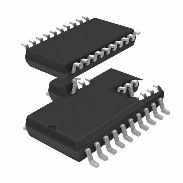
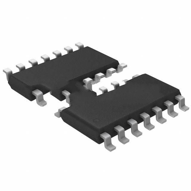
| Description | IC GATE DRIVER HALF BRIDG 20SOIC | IC GATE DVR HALF BRIDGE 14SOIC |
| Package | 20-SOIC (0.295", 7.50mm Width) | 14-SOIC (0.154", 3.90mm Width) |
| Series | - | - |
| Voltage - Supply | 10 V ~ 20 V | 10 V ~ 20 V |
| Operating Temperature | -40°C ~ 150°C (TJ) | -40°C ~ 150°C (TJ) |
| Mounting Type | Surface Mount | Surface Mount |
| Package / Case | 20-SOIC (0.295", 7.50mm Width) | 14-SOIC (0.154", 3.90mm Width) |
| Supplier Device Package | 20-SOIC | 14-SOIC |
| Input Type | Non-Inverting | Non-Inverting |
| Channel Type | 3-Phase | Synchronous |
| Rise / Fall Time (Typ) | 50ns, 30ns | 25ns, 15ns |
| Driven Configuration | Half-Bridge | Half-Bridge |
| Number of Drivers | 6 | 2 |
| Gate Type | IGBT, N-Channel MOSFET | IGBT, N-Channel MOSFET |
| Logic Voltage - VIL, VIH | 1V, 2.5V | 0.8V, 2.5V |
| Current - Peak Output (Source, Sink) | 350mA, 650mA | 2.5A, 2.5A |
| High Side Voltage - Max (Bootstrap) | 600V | 600V |
-
1. How to choose a gate driver for a MOSFET?
When selecting a gate driver for a MOSFET, the following key factors need to be considered:
Current drive capability: The current drive capability of the gate driver directly affects the turn-on and turn-off speed of the MOSFET. Higher current sinking and sourcing capabilities mean faster turn-on and turn-off speeds, thereby reducing switching losses.
Fault detection function: The gate driver should have fault detection functions such as undervoltage lockout (UVLO), desaturation (DESAT) detection, etc. to ensure the safety and stable operation of the system.
Interference immunity: Common mode transient immunity (CMTI) is an important parameter to measure the anti-interference ability of the gate driver. In high-power systems, high CMTI values can better resist voltage transients and ensure stable operation of the system.
Electrical isolation: Electrically isolated gate drivers can achieve electrical isolation between control signals and power devices to ensure system safety. Optical coupling isolation and magnetic coupling isolation are common electrical isolation technologies, and the selection should be compared according to application requirements.
Switching frequency: For high-frequency switching applications, the switching frequency of the gate driver should match the switching frequency of the MOSFET to ensure efficient operation.
Transmission delay: Transmission delay and transmission delay matching are important parameters of electrical isolation drivers, which affect the response speed of the signal and the stability of the system. -
2. What are the different types of gate drivers?
There are mainly the following types of gate drivers:
High-frequency high-voltage gate driver: This driver can drive two N-channel MOSFETs, supports a power supply voltage of up to 100V, has strong driving capabilities, is suitable for MOSFETs with high gate capacitance, and can reduce switching losses. It also has features such as undervoltage lockout and adaptive shoot-through protection.
HL-type gate driver: The HL-type driver drives two N-channel MOSFETs in a half-bridge configuration and supports a power supply voltage of up to 140V. It has independent control outputs and strong anti-interference ability, and is suitable for application scenarios that require independent control of two MOSFETs. The HL type driver also has functions such as UVLO, TTL/CMOS compatible input, adjustable turn-on/off delay and shoot-through protection.
Pulse transformer drive: This driver does not require a separate drive voltage, and applies a high voltage to the gate through a pulse transformer, which is suitable for half-bridge or full-bridge circuits. It uses a capacitor and pulse transformer in series to increase the switching speed, and quickly resets the pulse transformer through a Zener diode.
Optocoupler and floating power supply drive: This driver uses an optocoupler to isolate the microcontroller and power transistor, and requires a separate floating power supply. The optocoupler output requires a separate power supply, which is suitable for high-side drive of half-bridge or full-bridge.
Push-pull circuit: The push-pull circuit is suitable for situations where the drive current is insufficient. It provides sufficient drive current by alternating between two transistors, which is suitable for application scenarios that require high drive current.
Half-bridge/full-bridge high-end drive: This driver applies a high voltage to the gate, which is suitable for half-bridge or full-bridge circuits. Since the source voltage of the high-end MOSFET changes, it needs to be powered independently and cannot share a ground with the low-end MOSFET.
-
3. Why is a gate driver needed?
The main reasons for the need for gate drivers include signal amplification, electrical isolation, and protection mechanisms.
Signal Amplification
The main function of the gate driver is to convert the low-voltage signal of the controller into a high-voltage drive signal, thereby achieving effective control of the power device. This signal amplification function ensures that the power device can be stably turned on and off, improving the efficiency and reliability of the system.
Electrical Isolation
In many applications, electrical isolation between the control circuit and the power semiconductor is very important to prevent voltage feedback or ground loop problems. Gate drivers usually use optocouplers or other isolation methods to maintain this isolation, ensuring that the control circuit is not affected by the power circuit, thereby improving the stability and safety of the system.
Protection Mechanism
Gate drivers also integrate a variety of protection functions, such as overcurrent, overvoltage protection, and short-circuit protection. These protection mechanisms can effectively prevent power device damage and improve the reliability and safety of the system.
-
4. What is the difference between MOSFET and IGBT gate drivers?
The gate drivers of MOSFET and IGBT have significant differences in drive voltage, drive current, and drive mode.
Drive Voltage and Drive Current
MOSFET: The gate drive voltage of MOSFET is low, usually between 10V and 20V. Due to its structural characteristics, the driving current of MOSFET is also relatively small, which is suitable for using a smaller driving circuit.
IGBT: The gate driving voltage of IGBT is relatively high, usually between 15V and 20V. Due to its composite structure, IGBT requires a large driving current to control its conduction and cutoff, and usually requires a special driving circuit to provide sufficient driving power.
Driving method
MOSFET: The switching speed of MOSFET is very fast and suitable for high-frequency applications. Its driving method is relatively simple, and the gate can be directly controlled by voltage to achieve fast switching action.
IGBT: The switching speed of IGBT is slow and suitable for low-frequency applications. Due to its composite structure, IGBT requires a larger driving current and a more complex driving circuit to ensure its stable operation. IGBT usually requires positive and negative voltages to control its conduction and cutoff, especially when it is turned off, a negative voltage is required to eliminate the current tailing effect.
