RCME0561900BYS14 vs RCME0510001BYS14
| Part Number |
|
|
| Category | Through Hole Resistors | Through Hole Resistors |
| Manufacturer | Vishay Sfernice | Vishay Sfernice |
| Description | SFERNICE FIXED RESISTORS | SFERNICE FIXED RESISTORS |
| Package | Bag | Bag |
| Series | - | - |
| Features | - | - |
| Operating Temperature | - | - |
| Package / Case | - | - |
| Supplier Device Package | - | - |
| Tolerance | - | - |
| Temperature Coefficient | - | - |
| Size / Dimension | - | - |
| Power (Watts) | - | - |
| Height - Seated (Max) | - | - |
| Failure Rate | - | - |
| Resistance | - | - |
| Composition | - | - |
| Number of Terminations | - | - |

-
1. What are the packaging methods of through-hole resistors?
The DIP package is a double-row in-line package with two rows of pins arranged in parallel. DIP packages are widely used in integrated circuits, resistors, capacitors and other components, such as operational amplifiers, microcontrollers, etc.
The SIP package is a single-row in-line package with one row of pins. SIP packages are commonly used in resistor arrays, capacitor arrays and power modules. -
2. Resistor parameter marking
1. Direct marking method: directly mark the resistance value and allowable deviation of the resistor on the surface of the resistor. For chip resistors, 3-digit Arabic numerals are usually used to mark the resistance value, where the first digit represents the first significant digit of the resistance value, the second digit represents the second significant digit of the resistance value, and the third digit represents the multiple of the resistance value (that is, the number of 0s). For example, 203 represents 20kΩ, 471 represents 470Ω, and 105 represents 1MQ. For decimal ohms or integer values within 10Ω, specific symbols are also used, such as 1R2 represents 1.2Ω.
2. Text symbol method: Use three digits to mark the resistance value of the resistor, and no longer indicate the accuracy level (generally less than ±5%). This method is suitable for miniaturized electronic components, especially surface mount components and devices. For example, 3R9 represents 3.9Ω.
3. Digital method: Use three digits to represent the nominal value on the resistor, where the first and second digits are the effective value, and the third digit is the index (that is, the number of 0s), in ohms. Deviations are usually represented by text symbols.
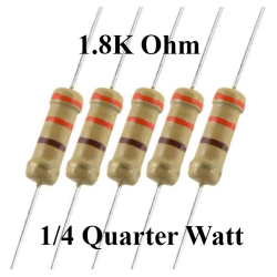
4. Color code method: Use different colored strips or dots to mark the nominal resistance value and allowable deviation on the surface of the resistor. This method is more common in foreign resistors. There is a fixed correspondence between color and value, such as black represents 0, brown represents 1, red represents 2, and so on. -
3. Resistor parameters
Through-hole resistor 10k/0.25w parameters
The parameters of the through-hole resistor 10k/0.25w include nominal resistance 10KΩ, rated power 0.25W, accuracy 1%, and installation type is through-hole.
Nominal resistance: 10KΩ, indicating that the basic resistance of the resistor is 10,000 ohms.
Rated power: 0.25W, meaning that the maximum power the resistor can withstand continuously is 0.25 watts.
Accuracy: 1%, indicating that the deviation between the actual resistance of the resistor and the nominal resistance does not exceed 1%.
Mounting type: through-hole, indicating that this resistor is suitable for through-hole installation, usually for through-hole installation on circuit boards. -
4. How to identify color ring resistors
1. Four-color ring resistors
Four-color ring resistors refer to resistors that use four color rings to indicate resistance, counting from left to right, as shown in the figure. The first color ring indicates the largest digit of the resistance; the second color ring indicates the second digit of the resistance; the third color ring indicates the number of times the resistance is multiplied; the fourth color ring indicates the allowable deviation (accuracy) of the resistance.
For example, if the first ring of a resistor is red (representing 2), the second ring is purple (representing 7), the third ring is brown (representing 10 times), and the fourth ring is gold (representing ±5%), then the resistance of this resistor should be 270Ω, and the error range of the resistance is ±5%.
2. Five-color ring resistor
Five-color ring resistor refers to a resistor that uses five color rings to represent the resistance, counting from left to right, as shown in the figure. The first color ring represents the largest digit of the resistance; the second color ring represents the second digit of the resistance; the third color ring represents the third digit of the resistance; the fourth color ring represents the multiplier of the resistance; the fifth color ring represents the error range.
For example, if a five-color ring resistor, the first ring is red (representing 2), the second ring is red (representing 2), the third ring is black (representing 0), the fourth ring is black (representing 1 times), and the fifth ring is brown (representing ±1%), then its resistance is 220Ω×1=220Ω, and the error range is ±1%.
3. Six-color ring resistors
Six-color ring resistors refer to resistors that use six color rings to represent resistance values. As shown in Figure 1, the first five color rings of the six-color ring resistor are the same as the five-color ring resistor, and the sixth color ring represents the temperature coefficient of the resistor.
