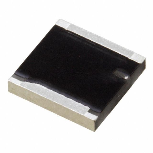
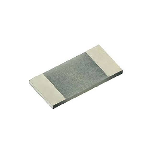
RP42525R0100GTTR vs PCNM2512K4R70FST5
| Part Number |
|
|
| Category | Chip Resistor - Surface Mount | Chip Resistor - Surface Mount |
| Manufacturer | KYOCERA AVX | Vishay Dale Thin Film |
| Description | RES SMD 100 OHM 2% 20W 2525 | RES SMD 4.7 OHM 1% 6W 2512 |
| Package | 2525 (6464 Metric) | Tape & Reel (TR) |
| Series | RP4 | PCNM |
| Operating Temperature | -55°C ~ 150°C | -55°C ~ 155°C |
| Package / Case | 2525 (6464 Metric) | 2512 (6432 Metric) |
| Supplier Device Package | 2525 | 2512 |
| Tolerance | ±2% | ±1% |
| Temperature Coefficient | 150ppm/°C | ±100ppm/°C |
| Size / Dimension | 0.245" L x 0.245" W (6.22mm x 6.22mm) | 0.259" L x 0.124" W (6.58mm x 3.15mm) |
| Power (Watts) | 20W | 6W |
| Height - Seated (Max) | 0.045" (1.15mm) | 0.018\" (0.46mm) |
| Resistance | 100 Ohms | 4.7 Ohms |
| Composition | Thin Film | Thin Film |
| Number of Terminations | 2 | 2 |
| Features | - | Flame Proof, Moisture Resistant, Non-Magnetic, Safety |
| Ratings | - | - |
| Failure Rate | - | - |

-
1. Chip fixed resistor classification?
1. Conventional series thick film chip resistors: including general-purpose resistors in sizes from 0201 to 0805, and resistors in sizes from 1206 to 2512.
2. High-precision and high-stability chip resistors: These resistors have high precision and high stability, with sizes ranging from 0201 to 0603, 0805 to 1210, and 2010 to 2512.
3. Conventional series thin film chip resistors: This refers to general-purpose thin film chip resistors with a wide range of sizes from 0201 to 2512.
4. Low resistance chip resistors: Suitable for circuit applications requiring low resistance values, with sizes ranging from 0402 to 1206, and 2010 to 2512.
5. Chip resistor arrays: Including raised and recessed chip resistor arrays, used in circuits that require multiple resistance values to work simultaneously.
6. Chip current sensor: used to detect the current in the circuit, with low temperature coefficient (TCR) characteristics. -
2. What is the number of chip resistors?
Chip resistors are one of the commonly used components in electronic circuits, and their digital identification is an important basis for identifying resistance values and accuracy. The digital identification is usually printed on the surface of the resistor and consists of several digits. These digits not only indicate the specific resistance value of the resistor, but also imply the tolerance accuracy information of the resistor.
-
3. Resistor digital identification interpretation example
To better understand the interpretation method of chip resistor digital identification, let's look at an example. Assuming that the digital identification on a chip resistor is "1001", what is the resistance value of this resistor? What is the accuracy?
First, we interpret the first three digits "100", indicating that the resistance value is 100 ohms. Next, we look at the last digit "1", which indicates that the tolerance accuracy of the resistor is 1%. Therefore, the resistance of this chip resistor is 100 ohms and the tolerance accuracy is ±1%. -
4. Chip Resistor package power relationship
Formula
Current = (rated power / resistance) square root
Power P = U2 / R
Package Rated power 70°C Maximum operating voltage (V) Imperial (inch) Metric (mm)
0201 0603 1/20W / 25
0402 1005 1/16W / 50
0603 1608 1/16W 1/10W 50
0805 2012 1/10W 1/8W 150
1206 3216 1/8W 1/4W 200
1210 3225 1/4W 1/3W 200
1812 4832 1/2W / 200
2010 5025 1/2W 3/4W 200
2512 6432 1W / 200
