Texas Instruments LM5113TME/NOPB

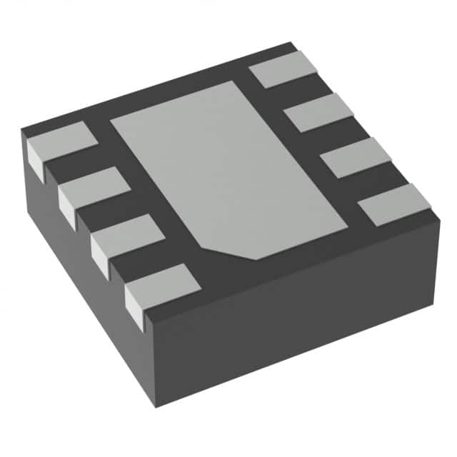
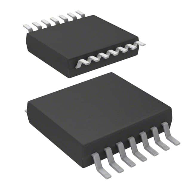
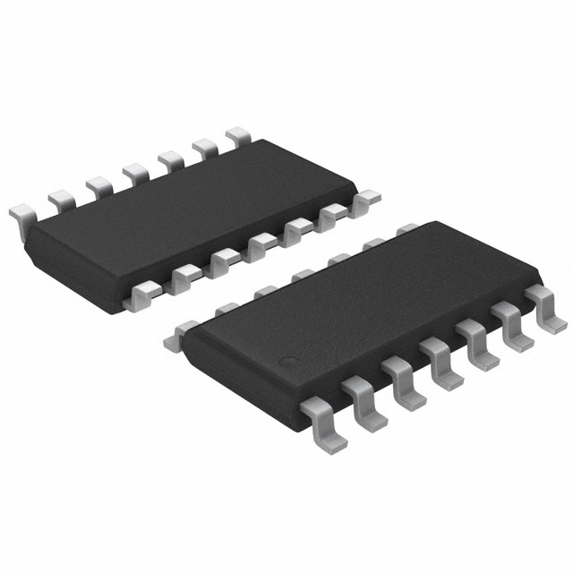
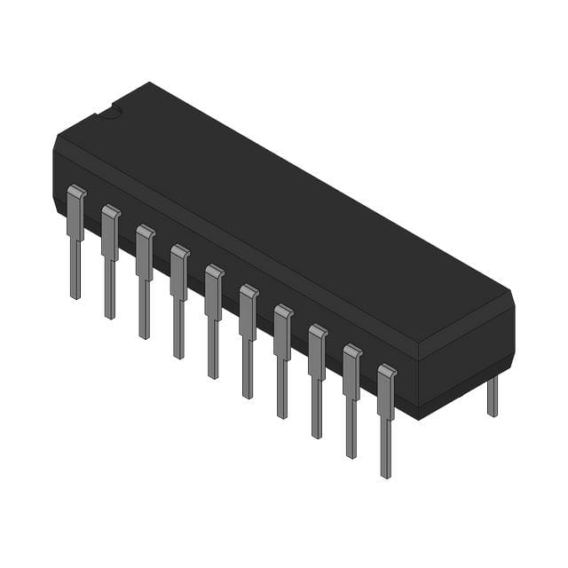
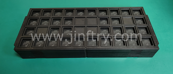
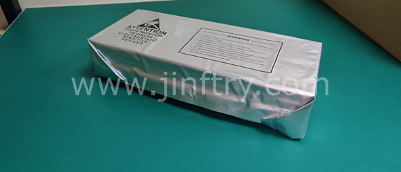
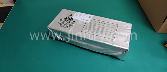
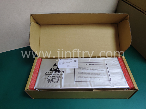
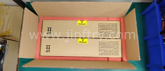
The picture is for reference only, please refer to the product specification
- LM5113TME/NOPB
- Texas Instruments
- IC GATE DRVR HALF-BRIDGE 12DSBGA
- PMIC - Gate Drivers
- LM5113TME/NOPB Datasheet
- 12-WFBGA, DSBGA
- -Reel®
-
 Lead free / RoHS Compliant
 - 15597
- Spot Inventory / Athorized Dstributor / Factory Excess Stock
- 1 year quality assurance 》
- Click to get rates


What is LM5113TME/NOPB
Texas Instruments Part Number LM5113TME/NOPB(PMIC - Gate Drivers), developed and manufactured by Texas Instruments, distributed globally by Jinftry. We distribute various electronic components from world-renowned brands and provide one-stop services, making us a trusted global electronic component distributor.
LM5113TME/NOPB is one of the part numbers distributed by Jinftry, and you can learn about its specifications/configurations, package/case, Datasheet, and other information here. Electronic components are affected by supply and demand, and prices fluctuate frequently. If you have a demand, please do not hesitate to send us an RFQ or email us immediately [email protected] Please inquire about the real-time unit price, Data Code, Lead time, payment terms, and any other information you would like to know. We will do our best to provide you with a quotation and reply as soon as possible.
LM5113TME/NOPB Specifications
- Part NumberLM5113TME/NOPB
- CategoryPMIC - Gate Drivers
- ManufacturerTexas Instruments
- DescriptionIC GATE DRVR HALF-BRIDGE 12DSBGA
- Package-Reel®
- Series-
- Voltage - Supply4.5V ~ 5.5V
- Operating Temperature-40°C ~ 125°C (TJ)
- Mounting TypeSurface Mount
- Package / Case12-WFBGA, DSBGA
- Supplier Device Package12-DSBGA
- Input TypeNon-Inverting
- Channel TypeIndependent
- Rise / Fall Time (Typ)7ns, 1.5ns
- Driven ConfigurationHalf-Bridge
- Number of Drivers2
- Gate TypeN-Channel MOSFET
- Logic Voltage - VIL, VIH1.76V, 1.89V
- Current - Peak Output (Source, Sink)1.2A, 5A
- High Side Voltage - Max (Bootstrap)107 V
Application of LM5113TME/NOPB
LM5113TME/NOPB Datasheet
LM5113TME/NOPB Datasheet , -Reel®,4.5V ~ 5.5V,-40°C ~ 125°C (TJ),Surface Mount,12-WFBGA, DSBGA,12-DSBGA,Non-Inverting,Independent,7ns, 1.5ns,Half-Bridge,2,N-Channel MOSFET,1.76V, 1.89V,1.2A, 5A,107 V
LM5113TME/NOPB Classification
PMIC - Gate Drivers
FAQ about PMIC - Gate Drivers
-
1. What is a gate driver?
Circuit, gate signal enhancement, controller
A gate driver is a circuit that is mainly used to enhance the gate signal of a field effect transistor (MOSFET) or an insulated gate bipolar transistor (IGBT) so that the controller can better control the operation of these semiconductor switches ,The gate driver controls the gate of the MOSFET or IGBT by converting the signal output by the controller into a high-voltage, high-current pulse, thereby improving the performance, reliability and service life of these devices.
Working principle
The gate driver is mainly composed of an input stage, a driver stage and an output stage:
Input stage: responsible for receiving the signal output by the controller and converting it into a TTL or CMOS logic level.
Driver stage: amplifies and converts the signal to generate a high-voltage, high-current pulse signal.
Output stage: uses these pulse signals to control the gate of the MOSFET or IGBT. -
2. How to choose a gate driver for a MOSFET?
When selecting a gate driver for a MOSFET, the following key factors need to be considered:
Current drive capability: The current drive capability of the gate driver directly affects the turn-on and turn-off speed of the MOSFET. Higher current sinking and sourcing capabilities mean faster turn-on and turn-off speeds, thereby reducing switching losses.
Fault detection function: The gate driver should have fault detection functions such as undervoltage lockout (UVLO), desaturation (DESAT) detection, etc. to ensure the safety and stable operation of the system.
Interference immunity: Common mode transient immunity (CMTI) is an important parameter to measure the anti-interference ability of the gate driver. In high-power systems, high CMTI values can better resist voltage transients and ensure stable operation of the system.
Electrical isolation: Electrically isolated gate drivers can achieve electrical isolation between control signals and power devices to ensure system safety. Optical coupling isolation and magnetic coupling isolation are common electrical isolation technologies, and the selection should be compared according to application requirements.
Switching frequency: For high-frequency switching applications, the switching frequency of the gate driver should match the switching frequency of the MOSFET to ensure efficient operation.
Transmission delay: Transmission delay and transmission delay matching are important parameters of electrical isolation drivers, which affect the response speed of the signal and the stability of the system. -
3. What are the different types of gate drivers?
There are mainly the following types of gate drivers:
High-frequency high-voltage gate driver: This driver can drive two N-channel MOSFETs, supports a power supply voltage of up to 100V, has strong driving capabilities, is suitable for MOSFETs with high gate capacitance, and can reduce switching losses. It also has features such as undervoltage lockout and adaptive shoot-through protection.
HL-type gate driver: The HL-type driver drives two N-channel MOSFETs in a half-bridge configuration and supports a power supply voltage of up to 140V. It has independent control outputs and strong anti-interference ability, and is suitable for application scenarios that require independent control of two MOSFETs. The HL type driver also has functions such as UVLO, TTL/CMOS compatible input, adjustable turn-on/off delay and shoot-through protection.
Pulse transformer drive: This driver does not require a separate drive voltage, and applies a high voltage to the gate through a pulse transformer, which is suitable for half-bridge or full-bridge circuits. It uses a capacitor and pulse transformer in series to increase the switching speed, and quickly resets the pulse transformer through a Zener diode.
Optocoupler and floating power supply drive: This driver uses an optocoupler to isolate the microcontroller and power transistor, and requires a separate floating power supply. The optocoupler output requires a separate power supply, which is suitable for high-side drive of half-bridge or full-bridge.
Push-pull circuit: The push-pull circuit is suitable for situations where the drive current is insufficient. It provides sufficient drive current by alternating between two transistors, which is suitable for application scenarios that require high drive current.
Half-bridge/full-bridge high-end drive: This driver applies a high voltage to the gate, which is suitable for half-bridge or full-bridge circuits. Since the source voltage of the high-end MOSFET changes, it needs to be powered independently and cannot share a ground with the low-end MOSFET.
We are a professional PCB manufacturer who offers comprehensive PCB manufacturing services including: professional Ceramic PCB HDI PCB Heavy Copper PCB High-TG PCB High Speed PCB High Frequency PCB Metal Core PCB PCB fabrication and PCB assembly, providing fast turnaround prototypes for high-end products.


• Prompt Responsiveness
• Guaranteed Quality
• Global Access
• Competitive Market Price
• One-Stop support services of supply chain
Jinftry, Your most trustworthy component supplier, welcome to send us the inquiry, thank you!
Do you have any questions about LM5113TME/NOPB ?
Feel free to contact us:
LM5113TME/NOPB Related Products

IC GATE DRVR HALF-BRIDGE 8MSOP