Vishay Sfernice RW13X70B123JB00

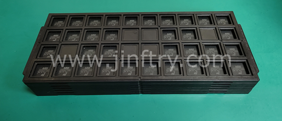
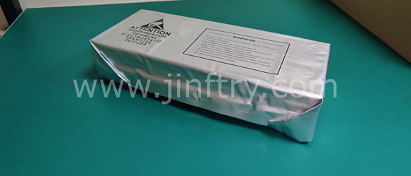
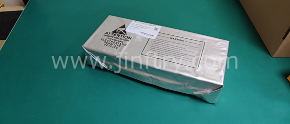
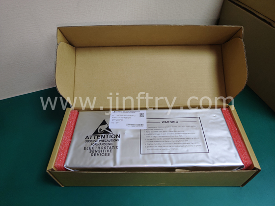
The picture is for reference only, please refer to the product specification
- RW13X70B123JB00
- Vishay Sfernice
- SFERNICE FIXED RESISTORS
- Through Hole Resistors
- RW13X70B123JB00 Datasheet
- -
- Box
-
 Lead free / RoHS Compliant
 - 5546
- Spot Inventory / Athorized Dstributor / Factory Excess Stock
- 1 year quality assurance 》
- Click to get rates


What is RW13X70B123JB00
Vishay Sfernice Part Number RW13X70B123JB00(Through Hole Resistors), developed and manufactured by Vishay Sfernice, distributed globally by Jinftry. We distribute various electronic components from world-renowned brands and provide one-stop services, making us a trusted global electronic component distributor.
RW13X70B123JB00 is one of the part numbers distributed by Jinftry, and you can learn about its specifications/configurations, package/case, Datasheet, and other information here. Electronic components are affected by supply and demand, and prices fluctuate frequently. If you have a demand, please do not hesitate to send us an RFQ or email us immediately [email protected] Please inquire about the real-time unit price, Data Code, Lead time, payment terms, and any other information you would like to know. We will do our best to provide you with a quotation and reply as soon as possible.
RW13X70B123JB00 Specifications
- Part NumberRW13X70B123JB00
- CategoryThrough Hole Resistors
- ManufacturerVishay Sfernice
- DescriptionSFERNICE FIXED RESISTORS
- PackageBox
- Series-
- Features-
- Operating Temperature-
- Package / Case-
- Supplier Device Package-
- Tolerance-
- Temperature Coefficient-
- Size / Dimension-
- Power (Watts)-
- Height - Seated (Max)-
- Failure Rate-
- Resistance-
- Composition-
- Number of Terminations-
Application of RW13X70B123JB00
RW13X70B123JB00 Datasheet
RW13X70B123JB00 Datasheet , Box
RW13X70B123JB00 Classification
Through Hole Resistors
FAQ about Through Hole Resistors
-
1. Resistor parameter marking
1. Direct marking method: directly mark the resistance value and allowable deviation of the resistor on the surface of the resistor. For chip resistors, 3-digit Arabic numerals are usually used to mark the resistance value, where the first digit represents the first significant digit of the resistance value, the second digit represents the second significant digit of the resistance value, and the third digit represents the multiple of the resistance value (that is, the number of 0s). For example, 203 represents 20kΩ, 471 represents 470Ω, and 105 represents 1MQ. For decimal ohms or integer values within 10Ω, specific symbols are also used, such as 1R2 represents 1.2Ω.
2. Text symbol method: Use three digits to mark the resistance value of the resistor, and no longer indicate the accuracy level (generally less than ±5%). This method is suitable for miniaturized electronic components, especially surface mount components and devices. For example, 3R9 represents 3.9Ω.
3. Digital method: Use three digits to represent the nominal value on the resistor, where the first and second digits are the effective value, and the third digit is the index (that is, the number of 0s), in ohms. Deviations are usually represented by text symbols.
4. Color code method: Use different colored strips or dots to mark the nominal resistance value and allowable deviation on the surface of the resistor. This method is more common in foreign resistors. There is a fixed correspondence between color and value, such as black represents 0, brown represents 1, red represents 2, and so on. -
2. Resistor parameters
Through-hole resistor 10k/0.25w parameters
The parameters of the through-hole resistor 10k/0.25w include nominal resistance 10KΩ, rated power 0.25W, accuracy 1%, and installation type is through-hole.
Nominal resistance: 10KΩ, indicating that the basic resistance of the resistor is 10,000 ohms.
Rated power: 0.25W, meaning that the maximum power the resistor can withstand continuously is 0.25 watts.
Accuracy: 1%, indicating that the deviation between the actual resistance of the resistor and the nominal resistance does not exceed 1%.
Mounting type: through-hole, indicating that this resistor is suitable for through-hole installation, usually for through-hole installation on circuit boards. -
3. What are the advantages of through-hole resistors?
Strong component connection: Through-hole technology passes through the circuit board through physical leads and is soldered on the other side, forming a strong connection that can resist mechanical stress. This makes through-hole resistors an excellent choice for components that are subject to physical strain, such as connectors, switches, or large, heavy components.
Reliable performance at high temperatures: Through-hole components are generally more resistant to extreme thermal environments, which is beneficial for applications that operate in high-temperature environments or undergo significant thermal cycles.
Easy to prototype and debug: Through-hole components are generally easier to use for manual assembly, prototyping, or testing. They can be manually inserted and soldered, making it easy to debug or modify prototypes.
Enhanced testability: Circuit boards designed with through-hole designs inherently provide excellent testability. The lead ends of the devices in the through-hole board also act as test nodes, which enables efficient online testing because the test probes can easily access them from the bottom. This makes it easier and more efficient to diagnose and fix any potential problems.
We are a professional PCB manufacturer who offers comprehensive PCB manufacturing services including: professional Ceramic PCB HDI PCB Heavy Copper PCB High-TG PCB High Speed PCB High Frequency PCB Metal Core PCB PCB fabrication and PCB assembly, providing fast turnaround prototypes for high-end products.


• Prompt Responsiveness
• Guaranteed Quality
• Global Access
• Competitive Market Price
• One-Stop support services of supply chain
Jinftry, Your most trustworthy component supplier, welcome to send us the inquiry, thank you!
Do you have any questions about RW13X70B123JB00 ?
Feel free to contact us:
RW13X70B123JB00 Related Products


RES 6.6666 OHM 0.05% 0.6W RADIAL