Build a simple robotic arm with ARM7 LPC2148 microcontroller
Build a simple robotic arm with ARM7 LPC2148 microcontroller
Robotic arms are one of those fascinating engineering creations, and it's always fascinating to watch these things tilt and translate to accomplish complex things like a human arm. These robotic arms are commonly found in industries that perform high-intensity mechanical work such as welding, drilling, painting, etc. on assembly lines, and more recently, advanced robotic arms with high precision have been developed to perform complex surgical procedures. So, in this tutorial, let's build a simple robotic arm using an ARM7-LPC2148 microcontroller to pick and place objects by manually controlling a few potentiometers.
3D printer robotic arm
ARM7-LPC2148
Get your 3D printed robotic arm ready
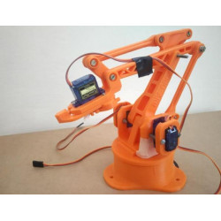
The 3D printed robotic arm used in this tutorial was made according to the design given by the EEZYbotARM available in Thingiverse. The full procedure to make the 3D printed robotic arm and the assembly details with video are in the thingiverse link shared above.
Here is an image of my 3D printed robotic arm assembled with 4 servo motors.
The circuit connections for this project are simple. Make sure to use a separate 5V DC power adapter to power the servo motors. For the potentiometers and buttons, we can use the 3.3V provided by the LPC2148 microcontroller.
Here we use the 4 ADC pins and 4 potentiometers of the LPC2148. The 4 PWM pins of the LPC2148 are connected to the PWM pins of the servo motor. We also connected 4 buttons to select which motor to operate. So when the button is pressed, the potentiometer changes to change the position of the servo motor.
One end of the button connected to the GPIO of LPC2148 is pulled down by a 10k resistor, and the other end is connected to 3.3V. 4 LEDs are also connected to indicate which servo motor is selected to change position.
Steps involved in programming the LPC2148 for a robotic arm
Before programming this robotic arm, we need to understand how to generate PWM in LPC2148 and use ADC in ARM7-LPC2148. To do this, see our previous project on connecting a servo motor with the LPC2148 and how to use the ADC in the LPC2148.
ADC conversion using LPC2148
Because we need to provide the ADC value to set the duty cycle value to generate the PWM output used to control the position of the servo motor. We need to find the ADC value of the potentiometer. Since we have four potentiometers to control the four servo motors, we need 4 ADC channels of the LPC2148. In this tutorial, we use the ADC pins (P0.25, P0.28, P0.29, P0.30) of the 4, 1, 2, 3 ADC channels present in the LPC2148 respectively.
Generating PWM Signals for Servo Motors Using LPC2148
Because we need to generate a PWM signal to control the position of the servo motor. We need to set the duty cycle of the PWM. We have four servo motors connected to the robotic arm, so we need 4 PWM channels from the LPC2148. In this tutorial, we use the PWM pins (P0.1, P0.7, P0.8, P0.21) of the 3, 2, 4, 5 PWM channels present in the LPC2148 respectively.
Program and flash the hex file to the LPC2148
To program the ARM7-LPC2148 we need the keil uVision and flash the HEX code to the LPC2148 requires the Flash Magic tool. The ARM7 STIck is programmed here using a USB cable via the micro USB port. We use Keil to code and create a hex file, then use Flash Magic to flash the HEX file to the ARM7 stick. To learn more about installing keil uVision and Flash Magic and how to use them.


