ERJ-2RKF1001X vs ERJ-2RKF2002X
| Part Number |

|
|
| Category | Chip Resistor - Surface Mount | Chip Resistor - Surface Mount |
| Manufacturer | Panasonic Electronic Components | Panasonic Electronic Components |
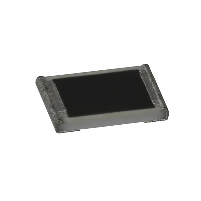
| Description | RES SMD 1K OHM 1% 1/10W 0402 | RES SMD 20K OHM 1% 1/10W 0402 |
| Package | Cut Tape (CT) | Cut Tape (CT) |
| Series | ERJ-2RK | ERJ-2RK |
| Features | Automotive AEC-Q200 | Automotive AEC-Q200 |
| Operating Temperature | -55°C ~ 155°C | -55°C ~ 155°C |
| Package / Case | 0402 (1005 Metric) | 0402 (1005 Metric) |
| Supplier Device Package | 0402 | 0402 |
| Tolerance | ±1% | ±1% |
| Temperature Coefficient | ±100ppm/°C | ±100ppm/°C |
| Size / Dimension | 0.039" L x 0.020" W (1.00mm x 0.50mm) | 0.039" L x 0.020" W (1.00mm x 0.50mm) |
| Power (Watts) | 0.1W, 1/10W | 0.1W, 1/10W |
| Ratings | AEC-Q200 | AEC-Q200 |
| Height - Seated (Max) | 0.016\" (0.40mm) | 0.016\" (0.40mm) |
| Failure Rate | - | - |
| Resistance | 1 kOhms | 20 kOhms |
| Composition | Thick Film | Thick Film |
| Number of Terminations | 2 | 2 |

-
1. What is a Chip Resistor?
Chip Resistor, also known as chip fixed resistors, are resistors designed for surface mounting. They can be mounted directly to the surface of a printed circuit board (PCB) without drilling holes like traditional through-hole components.
Such resistors are usually much smaller than traditional resistors, so they take up much less space on the circuit board. The use of SMD resistors is due to the invention of surface mount technology (SMT), which not only reduces the size of components, but also greatly reduces the time to manufacture circuits. SMD resistors are mainly used in professionally manufactured PCBs, while through-hole resistors are more commonly used in most homemade circuits because they are more convenient to install and do not require specialized equipment.
There are many ways to express the resistance value of SMD resistors, including direct marking, three-digit digital representation, four-digit digital representation, EIAJ code representation, etc. These methods enable the resistance value of the resistor to be clearly marked on the resistor for easy identification and use. In addition, SMD resistors are also resistant to moisture and high temperatures, and have a small temperature coefficient, which allows them to maintain good performance in various environments. -
2. How to choose Chip Resistor?
The application of surface mount technology (SMT) has been very common, and the proportion of electronic products assembled by SMT has exceeded 90%. my country began to introduce SMT technology in the 1980s. With the development of small SMT production equipment, the application scope of SMT is further expanding. Aviation, aerospace, instrumentation, machine tools and other fields are also using SMT to produce various small-volume electronic products or components.
In recent years, in addition to electronic product developers using SMT devices to develop new products, maintenance personnel have also begun to repair electronic products assembled by SMT technology in large quantities.
The models of SMT resistors are not uniform, and are set by each manufacturer, and the models are particularly long (consisting of more than a dozen English letters and numbers). If you can correctly propose various parameters and specifications of SMT resistors when purchasing, you can easily purchase (or order) the required resistors.
There are 5 parameters for SMT resistors, namely size, resistance, tolerance, temperature coefficient and packaging.
1. Size series SMT resistor series generally have 7 sizes, represented by two size codes. One size code is a 4-digit EIA (Electronics Industry Association) code, the first two digits and the last two digits represent the length and width of the resistor, in inches. The other is a metric code, also represented by 4 digits, in millimeters. Resistors of different sizes have different power ratings. Table 1 lists the codes and power ratings of these seven resistor sizes.
2. Resistance series The nominal resistance is determined by series. Each series is divided by the tolerance of the resistor (the smaller the tolerance, the more resistance divisions), among which the most commonly used is E-24 (the tolerance of the resistance value is ±5%), as shown in Table 2.
The resistance value is indicated by three digits on the surface of the chip resistor, of which the first and second digits are valid numbers, and the third digit indicates the number of zeros. When there is a decimal point, it is indicated by "R" and occupies one valid digit. The nominal resistance code representation method is shown in Table 3.
3. Tolerance The tolerance of chip resistors (carbon film resistors) has 4 levels, namely F level, ±1%; G level, ±2%; J level, ±5%; K level, ±10%.
4. Temperature coefficient The temperature coefficient of chip resistors has 2 levels, namely W level, ±200ppm/℃; X level, ±100ppm/℃. Only resistors with tolerance level F use level x, and resistors with tolerance levels of other levels are generally level w.
5. There are two main types of packaging: bulk and tape and roll.
The operating temperature range of chip resistors is -55--+125℃, and the maximum operating voltage is related to the size: 0201 is the lowest, 0402 and 0603 are 50V, 0805 is 150V, and other sizes are 200V.
6. The numbers on the surface of the chip resistors are arranged horizontally, and are specified to be represented by three digits, of which the first two are valid digits, and the third is the exponent of 10, in units of ohms. For example: 473 means 47×103=47 kΩ. If the second character on the surface of the resistor used to indicate the resistance value is the letter R, it represents a decimal point, for example: 5R1 means the resistance value is 5.1Ω. -
3. Resistor tolerance accuracy representation method
The tolerance accuracy of chip resistors refers to the allowable deviation range between the actual value of the resistor and the nominal value. In the digital identification, the tolerance accuracy is usually indicated by the last one or two digits. These numbers correspond to different accuracy levels, for example, 1% accuracy is usually indicated by the number "1", while 0.1% accuracy is indicated by the number "01".
-
4. Resistors Guide
When interpreting the digital identification of chip resistors, you need to pay attention to the following points:
1. Make sure to correctly identify each digit in the digital identification to avoid misreading and misjudging the resistance value or accuracy.
2. Be familiar with the digital representation methods corresponding to different accuracy levels so that you can quickly and accurately judge the tolerance accuracy of the resistor.
3. In actual applications, you also need to consider the operating temperature range, power and other parameters of the resistor to ensure its stable and reliable performance.
