How to measure resistance? And how to detect resistance
How to measure resistance? And how to detect resistance
1 Introduction:
There are usually many methods for measuring resistance, such as: ohmmeter, voltammetry, volt method, amperometric method, bridge method, substitution method, comparison method, semi-deviation method, etc. No matter which method is used, the experimental principle is nothing more than Ohm's law for partial circuits, Ohm's law for closed circuits, and the basic laws of series and parallel circuits.
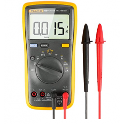
How to Measure Resistance with a Multimeter
2. Ohmmeter measures resistance:
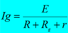
a The structural principle of an ohmmeter
The circuit is shown in the figure below. It consists of three components: G is an ammeter with internal resistance Rg and full bias current Ig. R is a variable resistor, also called a zeroing resistor. The electromotive force of the battery is E and the internal resistance is r.
The principle of ohmmeter is based on closed circuit Ohm's law. When the red and black test leads are connected to the resistance Rx to be measured, according to the closed circuit Ohm's law, we can get:
R, Rg, r are all fixed value resistors
There is a one-to-one functional relationship between the current I and the resistance to be measured Rx. The purpose of measuring the resistance can be achieved by measuring the current. Mark the resistor Rx value corresponding to the current I directly on the dial. The resistance of the resistor being measured can be read directly from the dial. Since I and Rx are nonlinear, the scaling is not uniform, and since it is a decreasing function, the scaling direction is opposite to the current range.

Ohmmeter circuit
b.Measurement methods and steps:
Preparation tools:
b1. Get a multimeter.
Make sure your multimeter's batteries are fully charged or new to ensure accuracy.
b2.Safety check:
Make sure the resistor you want to test is completely disconnected from the circuit, as measuring while powered may damage the multimeter or cause inaccurate measurements.
Check whether the multimeter leads are intact.
b3. Set up the multimeter:
Set the multimeter's function knob to the ohm (Ω) position. If your multimeter has multiple ohm settings, choose a setting that is slightly higher than the estimated resistance value to get a more accurate reading.
If your multimeter is auto-ranging, it will automatically select the best range.
b4. Zero position adjustment (if necessary):
If you are using an analog multimeter, you need to adjust the meter needle to zero before taking measurements.
Short-circuit the test leads so that the red and black test leads are in direct contact.
Adjust the zero adjustment knob on the multimeter so that the pointer points to zero.
b5. Measure resistance:
Connect the red test lead (usually positive) and the black test lead (usually negative) to both ends of the resistor.
Read the indicated value on the multimeter. If it is a digital multimeter, the reading will be displayed directly. If it is an analog multimeter, you need to read the scale pointed by the pointer.
b6. Record readings:
Write down the resistance value you read. If the reading on the dial is between two scales, record the value corresponding to the two scales and note that the actual reading should be between the two values.
b7. Verify measurement results:
You can change the multimeter's range and measure again to verify the accuracy of the results.
If the resistance value tested exceeds the measurement range of the multimeter, the multimeter will display an overflow prompt (such as 1 or OL). At this time, it is necessary to switch to a higher range and measure again.
Note: When using a multimeter to measure resistance, it is best to avoid direct contact with the wires or metal parts of the resistor with your fingers, because the resistance of the human body may also be read and affect the measurement results.
If you want to detect whether the resistor is damaged (such as open circuit or short circuit), you can use the following simple method:
Set the multimeter to the continuity test mode (usually there will be a sound prompt), touch both ends of the resistor with the test leads, if the resistor is intact, the multimeter will beep.
If it is an open circuit, the multimeter will not make any sound.
If there is a short circuit (resistance is very low or zero), the multimeter will beep continuously.
3. Voltammetry
3.1 Definition and principle: Voltammetry (Ohm's Law) is a basic law in electricity, proposed by German physicist Georg Simon Ohm in 1827. Voltammetry defines the relationship between current (I), voltage (V) and resistance (R) in a circuit,
The formula is: V=IR
Here: V is the voltage, the unit is Volt; I is the current through the conductor, the unit is Ampere; R is the resistance of the conductor, the unit is Ohm.
The principle of voltammetry states that when the temperature remains constant, the current through a conductor is directly proportional to the voltage applied across the conductor and inversely proportional to the resistance of the conductor. This relationship states that if the voltage increases and the resistance remains constant, the current through the conductor will also increase and vice versa.
3.2 Operation of measuring resistance by voltammetry
(1) Connect the circuit
A. Choose an electric meter with an appropriate range, that is, a sliding rheostat;
b. Select voltage dividing or current limiting circuit;
C. Determine whether the connection is internal or external;
d. Connect the circuit;
(2) Operation
Adjust the sliding rheostat, read the ammeter and voltmeter in sequence, and record the meter.
(3)Data processing
Method A. The individual resistors are calculated through mathematical calculations and then averaged to obtain the resistance value.
Method B. Record the read I and U on the graph paper respectively, establish the uI coordinate axis, and calculate the value of the resistance R by calculating the slope.
3.3 Selection of electricity meter and sliding rheostat
There is a basis for selecting a sliding rheostat in a voltage dividing circuit, that is, try to use a sliding rheostat with a smaller total resistance.
When the maximum resistance of the sliding rheostat is approximately equal to the resistance of the resistor under test, a voltage divider circuit must be selected.
When measuring with a voltmeter (ammeter), firstly, it is necessary to ensure that the measured data cannot exceed the maximum measurement value of the voltmeter (ammeter), and secondly, on the premise of ensuring the safety of the voltmeter, the accuracy of the measurement (ammeter) must be maximized. Therefore, the range of the voltmeter (ammeter) must be selected according to the size of the voltage (current) being measured.
When measuring, the maximum measured value of the ammeter or voltmeter should be higher than the actual value of the circuit under test, otherwise the ammeter or voltmeter will be easily damaged; but if it is much higher than the actual value of the circuit under test, the reading error will be large. Taking a pointer instrument as an example, the swing angle is limited. When measuring the same circuit, the higher the actual maximum measurement value of the ammeter or voltmeter is than the actual value of the circuit, the smaller the amplitude of the pointer swing will be, and therefore the greater the reading error will be.
3.4 Selection of voltage divider and current limiting circuit
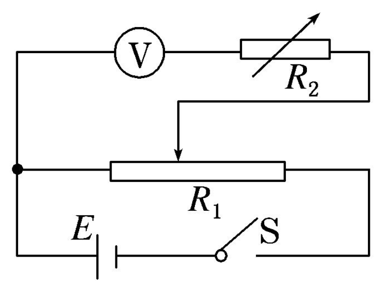
(1) Current limiting and voltage dividing circuit characteristics
Circuit schematic diagram:
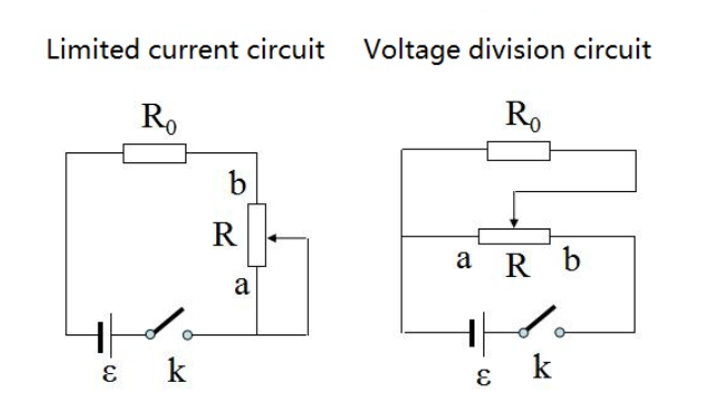
Current limiting and voltage division
The voltage variation range on R0 when the sliding head slides from a to b (set r = 0)
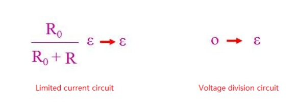
Voltage variation range
When the electric key is turned on, the initial position of the slider in the two circuits should be at terminal A.
3.5 Selection of internal connection method and external connection method
When the external method is selected, the voltmeter and resistor are connected in parallel. The voltmeter reads the voltage across the resistor, but the ammeter measures the total current through the resistor and the voltmeter, so the measured value is less than the true value. The actual measured resistance value is the resistance of the resistor and the resistance connected in parallel with the voltmeter. If the resistance of the resistor is much smaller than the internal resistance of the voltmeter, the current drawn by the voltmeter will be very small, and the current measured by the ammeter will be close to the current passing through the resistor, so the external method is suitable for measuring small resistances.
When the internal connection method is selected, the ammeter is connected in series with the resistor. The ammeter reading is the current value of the resistor, but the voltmeter measures the total voltage of the resistor and ammeter, so the measured value is greater than the true value. The total resistance value in series with the ammeter resistor. If the resistance value is much larger than the internal resistance of the ammeter, the voltage divided by the ammeter is very small, and the voltage measured by the voltmeter is close to the voltage across the resistor, so the internal connection method is suitable for measuring large resistances.
Current limiting and voltage dividing circuit diagram, internal connection method, external connection method
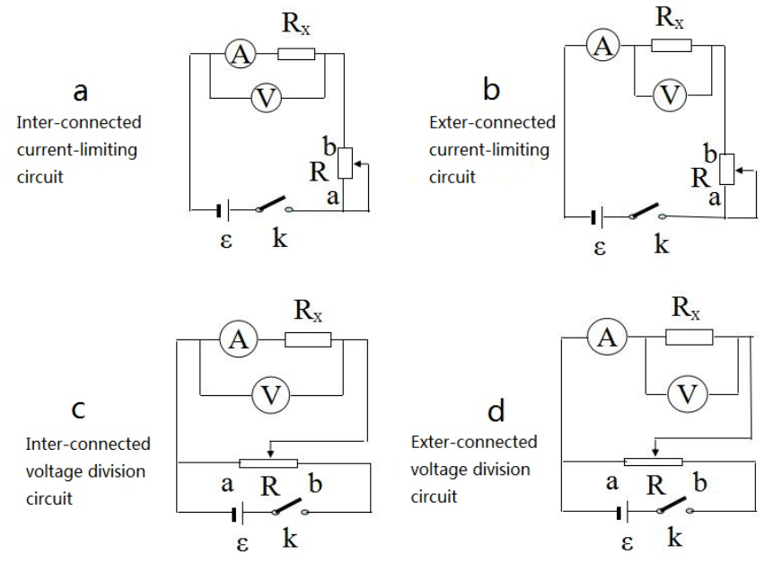
Interconnections and external connection circuits
4. Electric meter half-bias resistance measurement method
The meter has its own magical side - when it is connected to a circuit, it can display its own reading, so we can use its own reading changes (such as half bias) to cleverly measure its internal resistance. The half-bias method is commonly used to measure the internal resistance of an electric meter. For the half-bias method to measure the internal resistance of the instrument, there are the following two setting methods:
4.1 Ammeter half-bias method
(1)Experimental steps
①Connect the experimental circuit as shown in the figure;
②Open S 2, close S 1, and adjust R 1 so that the ammeter reading is equal to its range I m;
③Keep R 1 unchanged, close S 2, adjust R 2 so that the ammeter reading is equal to I m, and then read the value of R 2. If satisfies R 1 ≫ R A , then R A = R 2 .
(2) Experimental conditions: R 1 ≫ R A
(3)Measurement results: R A measurement value = R 2 < R A
(4) Error analysis
When S 2 is closed, the total resistance decreases and the total current increases, which is greater than the full bias current of the original ammeter. At this time, the ammeter is in a half-biased state, so the current flowing through R 2 is greater than the current in the branch where the ammeter is located. The resistance of R2 is greater than the ammeter. The resistance value is small, we regard the reading of R 2 as the internal resistance of the ammeter, so the measured internal resistance of the ammeter is too small.
4.2 Voltage meter half-bias method
(1)Experimental steps
Voltmeter half-bias method
Connect the experimental circuit as shown in the figure;
Adjust the value of R 2 to zero, close S, and adjust the sliding contact of R 1 so that the voltmeter reading is equal to its range U m;
Keeping the sliding contact of R1 stationary, adjust R2 so that the voltmeter reading is equal to 2(1) U m , and then read the value of R 2 . If R 1 <R V, then RV = R 2 can be considered.
(2) Experimental conditions: R 1 ≪ R V
(3) Measurement results: Measured R V=R 2 > R V
(4) Error analysis
When the value of R2 gradually increases from zero, the voltage across R2 and the voltmeter will also gradually increase, so when the voltmeter reading is equal to Um, the voltage across R2 will be greater than Um, making R2>RV, thus producing an RV measurement The value is too large. Obviously, the half-bias method is suitable for measuring the resistance of voltmeters with large internal resistance.
5. Several special methods for measuring resistance
5.1 AA method and VV method
Experimental principle
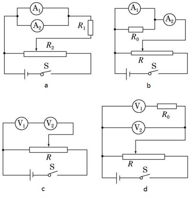
1. AA method (ammeter difference method)
(1) As shown in Figure a, two ammeters are connected in parallel. From I 1 r 1 = I 2 r 2, the internal resistance r 1 (or r 2 ) of the ammeter A 1 (or A 2 ) is found.
(2) As shown in Figure b, ammeter A 1 is connected in parallel with fixed value resistor R 0 , and then connected in series with ammeter A 2 . According to I 1 r 1 = ( I 2 - I 1 ) R 0 , the internal resistance r 1 of A 1 is obtained (this method is also called the ammeter difference method to measure the internal resistance of the ammeter).
2.VV method (voltmeter difference method)
(1) As shown in Figure C, connect two voltmeters in series, and according to r1(U1)=r2(U2), get the internal resistance of voltmeter V1 (or V2).
(2) As shown in Figure D, the voltmeter V1 is connected in series with the fixed value resistor R 0 and then in parallel with the voltmeter V2. According to U 2 = U 1 + r1 (U1) R 0, the internal resistance of the voltmeter V1 is obtained (this method is also called the voltmeter difference method to measure the internal resistance of the voltmeter).
5.2 Formula calculation method
It mainly uses the characteristics of series and parallel circuits and the knowledge of the entire circuit to analyze and calculate the value of the measured resistance. Figure 18 is a circuit for measuring resistance Rx. Rx is the resistance being measured, R is the protection resistor, and its resistance value is unknown. R1 is a known fixed resistor. The source electromotive force is unknown. S1 and S2 are single pole double throw switches. A is an ammeter without internal resistance.
DZ8
.Formula calculation method
(1) Measure Rx: S2 is close to d, S1 is close to a, and the ammeter reading I1 is recorded; then S2 is close to c, S1 is close to b, and the ammeter reading I2 is recorded.
(2)The calculation formula of Rx is:
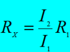
When S2 is connected to d and S1 is connected to a, the voltage of Rx is: Ux=I1Rx.
When S2 is connected to c and S1 is connected to b, the voltage on R1 U1=I2R2 does not change the resistance R, Ux=U1
So I1Rx=I2R1
5.3 Equivalent substitution method resistance measurement _ _ _
[Method Interpretation] Equivalent substitution method for measuring resistance: When measuring a resistance (or the internal resistance of an ammeter or voltmeter), use a resistance box instead of the resistance to be measured, if the two have the same impact on the circuit (such as when current or voltage equal)), the measured resistance is equivalent to the resistance box.
(1) Current equivalent replacement
The experimental steps of this method are as follows:
Connect the circuit according to the circuit diagram, adjust the resistance value of the resistor box R0 to the maximum, and place the slider P of the sliding varistor on terminal A.
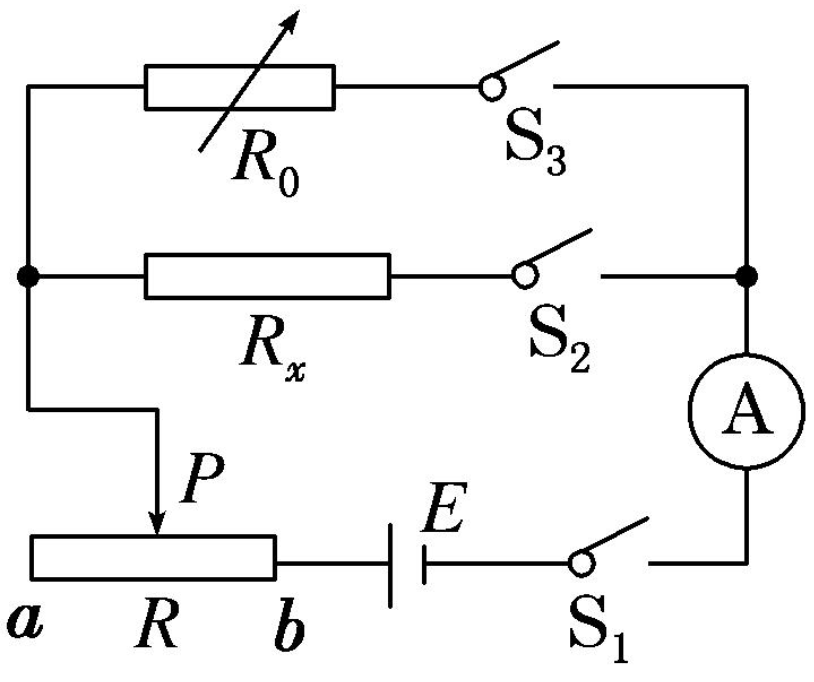
Current equivalent alternatives
Close the switches S 1 and S 2 and adjust the slider P so that the ammeter pointer is in the appropriate position. Note that the indication of the ammeter is I at this time.
Open the switch S2, then close the switch S3, keep the position of the sliding rheostat slider P unchanged, and adjust the resistance box so that the indication of the ammeter is still I.
At this time, the resistance R 0 of the resistor box connected to the circuit is equivalent to the resistance of the unknown resistor R x, that is, R x = R 0 .
5.4 Measuring resistance using a bridge circuit
(1) Principle:
The circuit shown in the figure below is called a bridge circuit. Under normal circumstances, current flows through the galvanometer, but when certain conditions are met, no current flows through the galvanometer. In this case, it is called bridge balancing. When the bridge is balanced, the potentials of A and B are equal, so the circuit structure can be seen as: R1R2 and R3R4 are connected in series and then in parallel; or R1R3 and R2R4 are connected in parallel and then in series.
bridge circuit
Bridge balance conditions: R1×R4=R2×R3
(2)Measurement method:
Connect the circuit, R1 and R2 are fixed value resistors, R3 is a variable resistor box (the value can be read directly), and Rx is the resistance to be measured. Adjust R3 so that the ammeter reads zero and apply balancing conditions to get the Rx value.
Note: Two points should be noted when measuring resistance using the bridge method. The first is to clarify the circuit structure. In the circuit, four resistors are connected in series, and an ammeter is connected in series in the middle. Then the part with the ammeter in series is the "bridge". The second thing is to clarify the conditions for bridge balance.
6. Different detection methods Resistors
(1) Detection of fixed resistance
① Connect two test leads (regardless of the positive and negative) to both ends of the resistor to detect the actual resistance value. In order to improve measurement accuracy, the range should be selected based on the nominal value of the resistance being measured. Due to the non-linear relationship of the ohm scale, the middle part is thinner. Therefore, the pointer indication value should be as low as possible to the middle part of the scale, that is, within the 20%-80% arc range at the beginning of full scale, so as to make the measurement more accurate. It varies based on the error level of the resistor. The allowable error between the reading and the nominal resistance value is (5%), (10%) or (20%) respectively. If not, outside the error range, the resistor value has changed.
② Note: When testing, especially when measuring resistances with resistances above tens of kΩ, do not touch the test leads and the conductive parts of the resistor; the detected resistance is welded from the circuit, and at least one head must be welded to avoid circuit damage. other components in . Affect the test and cause measurement errors. Although the resistance value of the color ring resistor can be judged by the color ring mark, it is best to use a multimeter to test the actual resistance value.
Related articles: Chip fixed resistors
(2) Detection of cement resistance
The methods and precautions for testing cement resistance are exactly the same as testing ordinary fixed resistors.
Related Articles: You can learn more about cement resistors in another article about resistor types.
(3) Detection of fuse resistor
In the circuit, when the fuse resistor melts, you can judge based on experience: if the surface of the fuse resistor is found to be black or burnt, it can be concluded that the load is too heavy and the current is too large. By exceeding the rated value many times; if the surface is open without any trace, it means that the current flowing is exactly equal to or slightly greater than its rated fuse value. The resistance of the fuse with no trace on the surface can be measured by using the Rx1 setting of the multimeter.
To ensure accurate measurements, one end of the fuse resistor should be soldered out of the circuit. If the measured resistance value is infinite, it means that the fuse resistance has been opened and failed. If the measured resistance value is significantly different from the nominal value, it indicates that the resistance value is not suitable for reuse. During the maintenance practice, it was found that a small number of resistors in the circuit were blown out, causing short circuits, so attention should be paid to detection.
(4) Detection of potentiometer
When checking the potentiometer, first turn the handle to see whether the handle rotates smoothly, whether the switch is flexible, whether the "click" sound is crisp when the switch is turned on or off, and listen to the sound of the internal contact point. The friction of the potentiometer and the friction of the resistor. If there is a "rustling" sound, it means the quality is not good. When testing with a multimeter, first select the appropriate electric block position of the multimeter based on the resistance of the potentiometer being tested, and then perform the following tests.
Use the ohm range of a multimeter to detect terminals "1" and "2". The reading should be the nominal resistance of the potentiometer. If the multimeter pointer does not move or the resistance value is different, the potentiometer is damaged.
Check whether the potentiometer boom and resistor are in good contact. Use the ohm block of the multimeter to detect both ends of "1" and "2" (or "2" and "3"), and turn the potentiometer shaft counterclockwise to a position close to the "off" button. The smaller the resistance value, the bigger the better.
(5) Detection of positive temperature coefficient thermistor
Room temperature detection (indoor temperature is close to 25°C): Measure the actual resistance of the two pins in contact with the PTC thermistor. Compare it with the nominal resistance. If the difference between the two is within ±2Ω, it is normal. If the actual resistance value is too different from the nominal resistance value, the actual resistance value has poor performance or is damaged.
Heating detection: Based on the normal temperature test, the second step of the test - heating detection, can be carried out. A heat source (such as an electric soldering iron) can be heated near the PTC thermistor. At the same time, use a multimeter to monitor whether the resistance value increases as the temperature increases. If the thermistor is normal and the resistance does not change, it means that its performance has deteriorated and cannot be used anymore. Be careful not to get the heat source too close to or in direct contact with the PTC thermistor to avoid burning it.
(6) Detection of negative temperature coefficient thermistor
The method of measuring the NTC thermistor with a multimeter is the same as that of measuring the ordinary fixed resistor, that is, selecting an appropriate electric potential barrier based on the nominal resistance of the NTC thermistor and directly measuring the actual value of Rt. However, since NTC thermistor is very sensitive to temperature, the following points should be paid attention to when testing:
Rt is measured by the manufacturer at an ambient temperature of 25°C. Therefore, when measuring Rt with a multimeter, it should also be done when the ambient temperature is close to 25°C to ensure the reliability of the test.
The measured power must not exceed the specified value to avoid measurement errors caused by current heating effects.
Pay attention to correct operation: Do not hold the thermistor body with your hands during testing to avoid body temperature affecting the test.
First measure the resistance value Rt1 at room temperature t1, and then use the electric iron as the heat source to measure the resistance value RT2 near the thermistor Rt. At the same time, use a thermometer to measure the average temperature t2 on the surface of the thermistor RT.
(7) Detection of varistor
Set the multimeter to 10K and connect the test leads to both ends of the resistor. The multimeter should show the resistance value indicated on the varistor. If this value is exceeded, the varistor is damaged.
As the voltage applied to the varistor increases, the varistor can change from MΩ (megaohms) to mΩ (milliohms). When the voltage is low, the varistor works in the leakage current region, showing a larger resistance value and smaller leakage current. When the voltage rises to the nonlinear region, the current changes within a large range and the voltage does not change much. Showing better voltage limiting characteristics; the voltage rises again, the varistor enters the saturation zone, showing smaller linear resistance. Due to the large current and long time, the varistor will overheat and burn out, or even burst.
(8) Detection of photoresistor
Black light film is used to cover the light-transmitting window of the photoresistor. At this time, the pointer of the multimeter remains basically unchanged, and the resistance value is close to infinity. The larger the value, the better the photoresistor performance. If the value is very small or close to zero, the photoresistor has been burned out and can no longer be used.
Aim the light source at the light-transmitting window of the photoresistor. The multimeter pointer should swing significantly and the resistance value should be significantly reduced. The smaller the value, the better the photoresistor performance. If the value is large or infinite, it indicates that the photoresistor has been damaged by an open circuit and cannot be used anymore.
Align the light-receiving window of the photoresistor with the incident light, shake the small black paper on the upper part of the light-shielding window of the photoresistor, and receive light intermittently. At this time, the pointer of the multimeter should swing left and right as the black paper shakes. If the multimeter pointer always stops at a certain position and does not swing with the shaking of the paper, it indicates that the photosensitive material of the photoresistor is damaged.
edit author:
![]()
Jinftry(Hong Kong registered company name: JING FU CAI (HONGKONG) INTERNATIONAL CO., LIMITED) was established in 2013, headquartered in Hong Kong, China, with a branch in Shenzhen, China. It is a global supplier of electronic components and a well-known and competitive electronic product distributor in Asia. Is also an excellent strategic partner of global ODM/OEM/EMS, able to quickly find authentic and traceable electronic components for customers to purchase.


