ON Ethernet Surge Protection Solutions
ON Ethernet Surge Protection Solutions
We're using Gigabit Ethernet, or at least 100M Fast Ethernet over hundreds of meters. Run miles of cables in the walls of our work buildings or their ceilings or other hidden spaces. We use Power over Ethernet (PoE) to power and communicate with devices on rooftops, kiosks, light poles, and even communication towers. When your boss tells you Ethernet to replace the IEEE-488 bus link in the factory, he probably doesn't understand the inherent robustness and stability of the IEEE-488 link and what you need to do to keep your Ethernet Network networks operate in an industrial environment. At this time, you also need a network line protection scheme. As the security guard of the network, it can provide years of trouble-free service.
From a practical point of view, most Ethernet interfaces do not require special protection. Because the first electrical part behind most RJ-45 Ethernet jacks is an isolation transformer, which provides some protection. This, combined with the ESD protection built into most Ethernet PHY transceiver ICs, provides adequate protection in most home and office environments. The problem is that typically Ethernet interfaces are exposed to a relatively low percentage of serious threats. Long cables inside buildings become long antennas that can couple energy from lightning strikes into the network. If they are exposed outdoors e.g. kiosks, or surveillance cameras on roofs or roofs. These "antennas" can even harvest lightning energy.
When safety and reliability issues first surfaced, some circuit protection companies developed "dongles" solutions to provide additional ESD overvoltage protection. When the "dongle" is plugged into the RJ-45 jack in question, a surge protected RJ-45 jack is provided. They are added to routers or other devices that experience failures and are effective to a certain extent.
With the increase in data transfer rates and the advent of "PoE" technology, this requires customized solutions. Previously the pure "dongle" approach was often insufficient. However, there are some problems with "PoE" technology. Because, the presence of DC voltage will trip the overvoltage protection of transceivers designed for 2V Ethernet signaling. Gigabit data rates can suffer severe data errors due to the capacitive loading of protection schemes designed for 10Base-T or 100Base-T networks. While "PoE" provides overcurrent protection, these systems are also vulnerable to electrical transients that can damage other types of power equipment.
Unlike 10Base-T, Gigabit Ethernet uses a complex encoding scheme that requires a very linear channel to transmit over long distances. Depending on the applied voltage, silicon diodes and thyristors typically exhibit nonlinear capacitance. Gigabit Ethernet also uses a clock frequency that is more than 10 times faster than Fast Ethernet, which makes the signal more sensitive to the capacitance of cables and any protective equipment used.
Building a strong Ethernet protection system usually requires a "layered" design approach, using a power + network two-in-one integrated design, multi-level protection circuit It consists of the first layer, the second layer and sometimes the third layer . Each level corresponds to a different task:
The first layer: thyristor or silicon process device. Such as Littelfuse's SDP-Q38CB wideband SIDACtor protection thyristor. It provides the required surge handling capability with minimal capacitive loading. The SIDACtor protection thyristor has minimal influence on the data signal. Innovative silicon design enables capacitive load characteristics for high bandwidth applications. The surge capability of the surface mount QFN package with the SO-8 footprint exceeds most of the world's most widely used building interior standards and recommended standards for surge withstand of secondary side protectors. These thin thyristors have low distortion and low insertion loss, although, the primary layer passes excessive voltages, but it does limit the duration of the surge because most of the energy is shunted to ground. For "PoE" applications, the breakdown voltage of the protective device must be higher than the "PoE" supply voltage. In addition, the design engineer must ensure that after the protection is activated, the primary protection system will "exit" or "reset" when connected to power. Typically, this requires a foldback current-limited "PoE" power supply with the protection device in a high hold current state.
Layer 2: High frequency transformer isolation, which not only provides DC isolation for the PHY transceiver ICs, but their tiny magnetic cores tend to saturate, limiting the amount of energy coupled into the transceiver circuitry. However, the isolation between the coils must be able to withstand the energized voltage of the primary layer without failure. Keep in mind that the DC breakdown voltage of a GDT may be 90V, but may exceed 500V under fast lightning strike conditions. The inter-coil capacitance can also couple energy through the isolation barrier, but this is usually less than the magnetic coupling energy.
Layer 3: While primary and secondary protection units have removed "PoE" power and limited maximum voltage and current to manageable levels, many of these techniques are borrowed from ESD protection device technology.
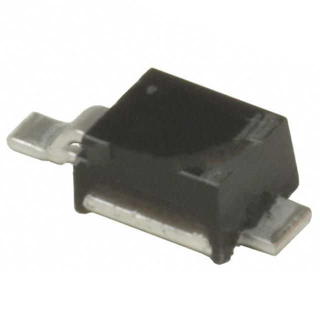
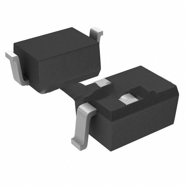
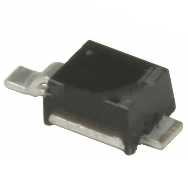
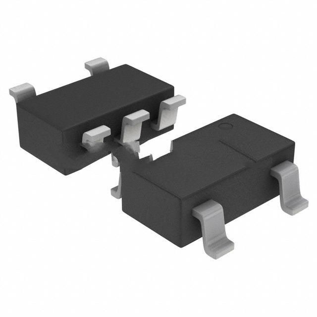
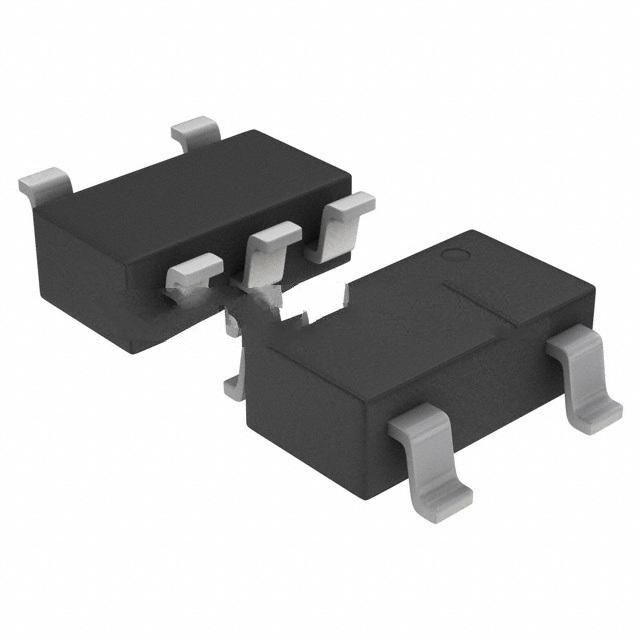
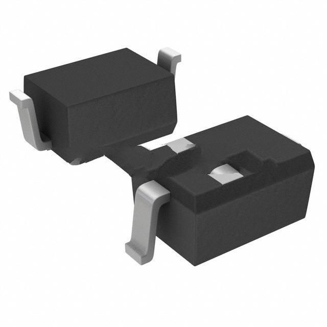
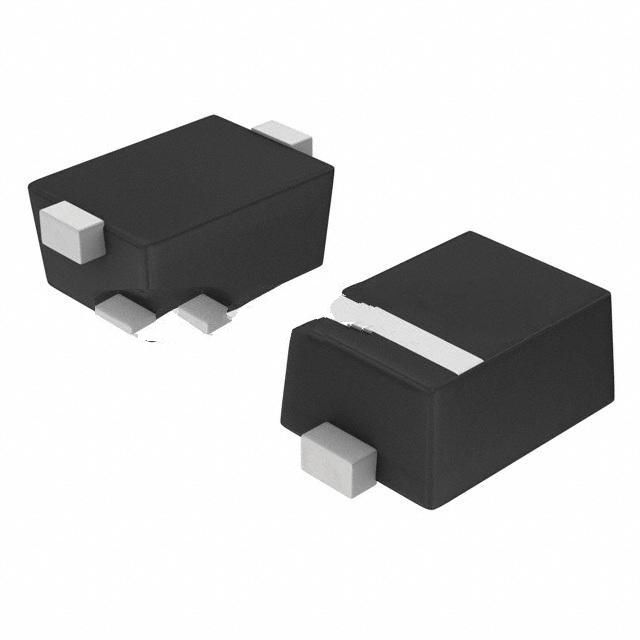
ON Semiconductor's NUP4114 family of products are used to protect voltage sensitive components and high-speed data from ESD. Features ultra-low capacitance, excellent clamping capability, low leakage current, and fast response.

