AD7478ARTZ-REEL7 vs AD7170BCPZ-REEL7
| Part Number |
|
|
| Category | Data Acquisition - Analog to Digital Converters (ADC) | Data Acquisition - Analog to Digital Converters (ADC) |
| Manufacturer | Analog Devices Inc. | Analog Devices Inc. |
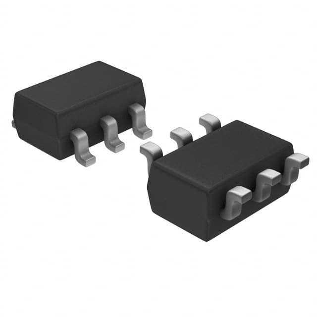
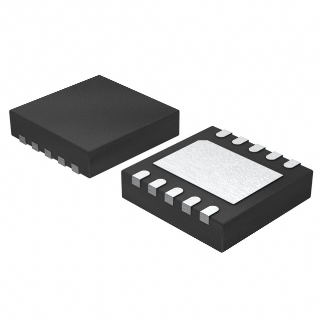
| Description | IC ADC 8BIT SAR SOT23-6 | IC ADC 12BIT SIGMA-DELTA 10LFCSP |
| Package | Tape & Reel (TR) | Cut Tape (CT) |
| Series | - | - |
| Features | - | - |
| Operating Temperature | -40°C ~ 85°C | -40°C ~ 105°C |
| Mounting Type | Surface Mount | Surface Mount |
| Package / Case | SOT-23-6 | 10-VFDFN Exposed Pad, CSP |
| Supplier Device Package | SOT-23-6 | 10-LFCSP-WD (3x3) |
| Reference Type | Supply | External |
| Sampling Rate (Per Second) | 1M | - |
| Data Interface | SPI, DSP | SPI |
| Number of Bits | 8 | 12 |
| Voltage - Supply, Analog | 2.7V ~ 5.25V | 2.7V ~ 5.25V |
| Voltage - Supply, Digital | 2.7V ~ 5.25V | 2.7V ~ 5.25V |
| Number of Inputs | 1 | 1 |
| Input Type | Single Ended | Differential |
| Configuration | S/H-ADC | ADC |
| Ratio - S/H:ADC | 1:1 | - |
| Number of A/D Converters | 1 | 1 |
| Architecture | SAR | Sigma-Delta |
-
1. How many types of ADC are there?
The types of ADC (Analog-to-Digital Converter) mainly include:
1. Integral ADC: Its working principle is to convert the input voltage into time (pulse width signal) or frequency (pulse frequency), and then obtain the digital value by the timer/counter. The advantage of the integral ADC is that it can obtain high resolution with a simple circuit and has strong anti-interference ability, but the disadvantage is that the conversion rate is extremely low because the conversion accuracy depends on the integration time.
2. Successive approximation type (SAR ADC): The successive approximation ADC is one of the most common architectures. Its basic principle is to convert by gradually approximating the value of the analog input signal. The advantages of the successive approximation ADC are high speed and low power consumption. It is cheap at low resolution, but expensive at high precision.
3. Parallel comparison type/serial-parallel comparison type ADC: The parallel comparison type AD uses m -
2. What process converts analog to digital?
There are three basic processes for analog to digital conversion:
The first process is "sampling", which is to extract the sample value of the analog signal at equal intervals to turn the continuous signal into a discrete signal.
The second process is called "quantization", which is to convert the extracted sample value into the closest digital value to represent the size of the extracted sample value.
The third process is "encoding", which is to represent the quantized value with a set of binary digits. After these three processes, the digitization of the analog signal can be completed. This method is called "pulse encoding".
After the digital signal is transmitted to the receiving end, a restoration process is required, that is, the received digital signal is converted back to an analog signal so that it can be understood by the receiver. This process is called "digital-to-analog conversion", which reproduces it as sound or image. -
3. What is the principle of analog-to-digital converters?
The working principle of the analog-to-digital converter (ADC) is to convert analog signals into digital signals through four processes: sampling, holding, quantization, and encoding.
The main components of the analog-to-digital converter include samplers and quantizers, which work together to convert continuous analog signals into discrete digital signals. This process requires a reference analog quantity as a standard, and the maximum convertible signal size is usually used as the reference standard. The basic principles of the analog-to-digital converter can be summarized as follows:
Sampling: The analog-to-digital converter first samples the input analog signal through a sampling circuit, that is, discretizes the analog signal on the time axis.
Holding: The sampled signal is held by the holding circuit for the next quantization and encoding process.
Quantization: The quantization process is to divide the amplitude of the sampled and held analog signal into a finite number of le -
4. What is the difference between ADC and DAC?
The main difference between ADC and DAC is that they process different types of signals and conversion directions.
The main function of an ADC (analog-to-digital converter) is to convert analog signals into digital signals. This process involves sampling, quantization, and encoding, where sampling is the periodic measurement of the value of an analog signal at a certain sampling rate, quantization is the conversion of the sampled continuous values into a finite number of discrete levels, and encoding is the conversion of the quantized discrete levels into binary code. The output of the ADC is a digital signal that can be processed and stored by a computer or other digital circuit for various applications such as digital signal processing, data logging, and communications. Common applications in life include microphones, digital thermometers, digital cameras, etc., which convert the actual perceived analog information into digital signals for further processing and analysis12.
DAC (
