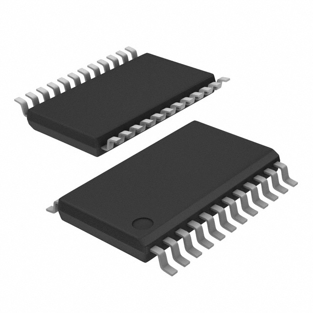
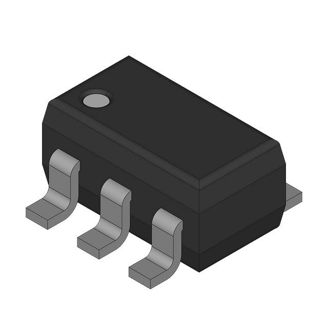
ADC1175CIMTCX/NOPB vs ADC121S021CIMFX/NOPB
| Part Number |
|
|
| Category | Data Acquisition - Analog to Digital Converters (ADC) | Data Acquisition - Analog to Digital Converters (ADC) |
| Manufacturer | Texas Instruments | National Semiconductor |
| Description | IC ADC 8BIT TWO-STEP 24TSSOP | ADC121S021 SINGLE CHANNEL, 50 TO |
| Package | Tape & Reel (TR) | Bulk |
| Series | - | - |
| Features | - | - |
| Operating Temperature | -20°C ~ 75°C | -40°C ~ 85°C |
| Mounting Type | Surface Mount | Surface Mount |
| Package / Case | 24-TSSOP (0.173\", 4.40mm Width) | SOT-23-6 |
| Supplier Device Package | 24-TSSOP | SOT-23-6 |
| Reference Type | External, Internal | Supply |
| Sampling Rate (Per Second) | 20M | 200k |
| Data Interface | Parallel | SPI, DSP |
| Number of Bits | 8 | 12 |
| Voltage - Supply, Analog | 5V | 2.7V ~ 5.25V |
| Voltage - Supply, Digital | 5V | 2.7V ~ 5.25V |
| Number of Inputs | 1 | 1 |
| Input Type | Single Ended | Single Ended |
| Configuration | S/H-ADC | S/H-ADC |
| Ratio - S/H:ADC | 1:1 | 1:1 |
| Number of A/D Converters | 1 | 1 |
| Architecture | Two-Step | SAR |
-
1. How does ADC convert analog to digital?
The technology that converts analog sound signals into digital signals is called analog-to-digital conversion technology (Analog to Digital Converter, referred to as ADC). The function of ADC is to convert continuously changing analog signals into discrete digital signals. The process of analog-to-digital conversion can be completed by steps such as sampling, holding, quantization, and encoding.
-
2. What are DAC and ADC?
ADC and DAC are two important concepts in digital electronics. ADC stands for "analog-to-digital converter", which can convert analog signals into digital signals. DAC stands for "digital-to-analog converter", which can convert digital signals into analog signals. Both converters play an important role in many electronic products, such as mobile phones, televisions, stereos, etc.
-
3. How to convert analog to digital without ADC?
Analog to digital conversion without ADC can be achieved through PWM circuit. This method is suitable for those main control chips without built-in ADC, which needs to be solved by two GPIOs and an operational amplifier. The basic principle is to use an integral circuit to convert the PWM wave into a smooth DC voltage, and then continuously adjust the PWM duty cycle by comparing it with the voltage to be measured until the output of the comparator changes from 0 to 1, and record the current PWM duty cycle, thereby realizing the measurement of the analog voltage.
-
4. What is the principle of analog-to-digital converters?
The working principle of the analog-to-digital converter (ADC) is to convert analog signals into digital signals through four processes: sampling, holding, quantization, and encoding.
The main components of the analog-to-digital converter include samplers and quantizers, which work together to convert continuous analog signals into discrete digital signals. This process requires a reference analog quantity as a standard, and the maximum convertible signal size is usually used as the reference standard. The basic principles of the analog-to-digital converter can be summarized as follows:
Sampling: The analog-to-digital converter first samples the input analog signal through a sampling circuit, that is, discretizes the analog signal on the time axis.
Holding: The sampled signal is held by the holding circuit for the next quantization and encoding process.
Quantization: The quantization process is to divide the amplitude of the sampled and held analog signal into a finite number of le
