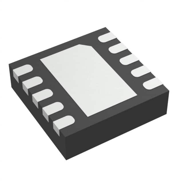
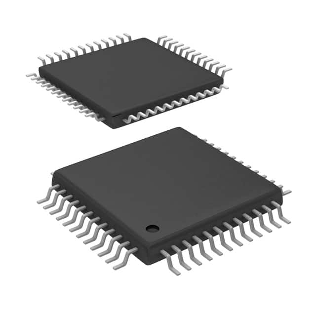
ADS8881IDRCR vs ADS7890IPFBT
| Part Number |
|
|
| Category | Data Acquisition - Analog to Digital Converters (ADC) | Data Acquisition - Analog to Digital Converters (ADC) |
| Manufacturer | Texas Instruments | Texas Instruments |
| Description | IC ADC 18BIT SAR 10VSON | IC ADC 14BIT SAR 48TQFP |
| Package | Tape & Reel (TR) | Bulk |
| Series | microPOWER™ | - |
| Features | - | - |
| Operating Temperature | -40°C ~ 85°C | -40°C ~ 85°C |
| Mounting Type | Surface Mount | Surface Mount |
| Package / Case | 10-VFDFN Exposed Pad | 48-TQFP |
| Supplier Device Package | 10-VSON (3x3) | 48-TQFP (7x7) |
| Reference Type | External | External, Internal |
| Sampling Rate (Per Second) | 1M | 1.25M |
| Data Interface | SPI | SPI |
| Number of Bits | 18 | 14 |
| Voltage - Supply, Analog | 2.7V ~ 3.6V | 5V |
| Voltage - Supply, Digital | 2.7V ~ 3.6V | 2.7V ~ 5.25V |
| Number of Inputs | 1 | 1 |
| Input Type | Differential | Pseudo-Differential |
| Configuration | S/H-ADC | S/H-ADC |
| Ratio - S/H:ADC | 1:1 | 1:1 |
| Number of A/D Converters | 1 | 1 |
| Architecture | SAR | SAR |
-
1. How many types of ADC are there?
The types of ADC (Analog-to-Digital Converter) mainly include:
1. Integral ADC: Its working principle is to convert the input voltage into time (pulse width signal) or frequency (pulse frequency), and then obtain the digital value by the timer/counter. The advantage of the integral ADC is that it can obtain high resolution with a simple circuit and has strong anti-interference ability, but the disadvantage is that the conversion rate is extremely low because the conversion accuracy depends on the integration time.
2. Successive approximation type (SAR ADC): The successive approximation ADC is one of the most common architectures. Its basic principle is to convert by gradually approximating the value of the analog input signal. The advantages of the successive approximation ADC are high speed and low power consumption. It is cheap at low resolution, but expensive at high precision.
3. Parallel comparison type/serial-parallel comparison type ADC: The parallel comparison type AD uses m -
2. When is ADC used?
ADC (Analog-to-Digital Converter) is widely used in a variety of scenarios, including but not limited to:
Sensor interface: For example, temperature sensors, pressure sensors, and light sensors, ADC converts analog voltages into digital signals for the use of digital thermometers, temperature control systems, barometers, air pressure sensing systems, light intensity detection and control systems.
Audio signal processing: In microphones, ADC converts analog audio signals into digital signals for digital audio processing, recording, and playback.
Medical equipment: Such as electrocardiograms (ECGs) and oximeters, ADC converts analog signals of ECG signals and blood oxygen saturation into digital signals for heart health monitoring and diagnosis and blood oxygen level monitoring.
Data acquisition system: In various applications that need to collect data from analog signals, ADC is used to convert analog signals into digital signals for storage, processing, and analysis. -
3. What is the difference between ADC and DAC?
The main difference between ADC and DAC is that they process different types of signals and conversion directions.
The main function of an ADC (analog-to-digital converter) is to convert analog signals into digital signals. This process involves sampling, quantization, and encoding, where sampling is the periodic measurement of the value of an analog signal at a certain sampling rate, quantization is the conversion of the sampled continuous values into a finite number of discrete levels, and encoding is the conversion of the quantized discrete levels into binary code. The output of the ADC is a digital signal that can be processed and stored by a computer or other digital circuit for various applications such as digital signal processing, data logging, and communications. Common applications in life include microphones, digital thermometers, digital cameras, etc., which convert the actual perceived analog information into digital signals for further processing and analysis12.
DAC ( -
4. What is the difference between the input and output of an ADC?
The input of ADC (Analog-to-Digital Converter) is analog quantity and the output is digital quantity.
The main function of ADC is to convert continuous analog signal into discrete digital signal. In electronic systems, analog signal usually refers to continuously changing voltage or current, such as the signal obtained from microphone or sensor. The amplitude and frequency of these analog signals can change continuously, while digital signals are composed of a series of discrete values, usually expressed in binary form.
Input: The input of ADC receives analog signals, which can be in the form of continuously changing physical quantities such as voltage and current. The amplitude and frequency of analog signals can change continuously, such as the voltage range from 0V to 5V.
Output: The output of ADC is digital signal, which is composed of a series of discrete values, usually expressed in binary form. The advantage of digital signals is that they can be calculated and processed quic
