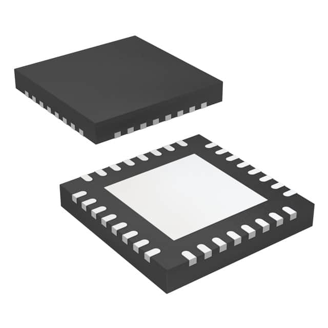
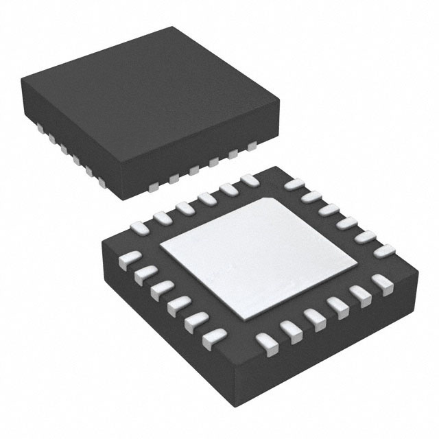
LMK00334RTVRQ1 vs SI5338C-B03798-GM
| Part Number |
|
|
| Category | Clock/Timing - Application Specific | Clock/Timing - Application Specific |
| Manufacturer | Texas Instruments | Skyworks Solutions Inc. |
| Description | IC CLK BUF 400MHZ 1CIRC 32WQFN | I2C CONTROL, 4-OUTPUT, ANY FREQU |
| Package | Tube | Tube |
| Series | Automotive, AEC-Q100 | MultiSynth™ |
| Voltage - Supply | 3.15V ~ 3.45V | - |
| Operating Temperature | -40°C ~ 105°C | - |
| Mounting Type | Surface Mount | Surface Mount |
| Package / Case | 32-WFQFN Exposed Pad | 24-VFQFN Exposed Pad |
| Supplier Device Package | 32-WQFN (5x5) | 24-QFN (4x4) |
| Output | HCSL, LVCMOS | - |
| Frequency - Max | 400MHz | - |
| Number of Circuits | 1 | - |
| Input | CML, HCSL, HSTL, LVDS, LVPECL, SSTL, Crystal | - |
| PLL | No | - |
| Main Purpose | PCI Express (PCIe) | - |
| Ratio - Input:Output | 3:5 | - |
| Differential - Input:Output | Yes/Yes | - |
-
1. What ICs are used in digital clocks?
ICs used in digital clocks include LM8361, LM8363, LM8365, LM8560, and MM5456. These ICs are mainly used for the timing and display functions of digital clocks.
LM8361, LM8363, and LM8365 use a common cathode display board, while LM8560 and MM5456 use a dual power supply display pole, which has the characteristics of fewer pins, 28 and 22 pins 1 respectively. In addition, digital clocks may also use other types of ICs, such as DS1629, SY75572LMG, AD9522-5BCPZ, etc. These ICs have different functions and characteristics and are suitable for different application scenarios.
The basic components of a digital clock include four parts: a multivibrator, a counter, a decoder, and a digital display. The multivibrator is used to generate a second pulse signal, the counter is used to record seconds, minutes, and hours, the decoder converts the output of the counter into a digital display, and the digital display is used to display the time.
-
2. What kind of IC is used for a timer?
The commonly used ICs for timers include 555 timer chips, 556 dual 555 timer chips, 74HC series chips, CD4000 series chips, RTC chips, and PLL chips.
The 555 timer chip is a common timing IC that is often used in timers, pulse generators, and oscillation circuits. It was launched by Signetics in 1971 and is widely used in the design of electronic circuits due to its ease of use, low price, and good reliability. A 555 timer can realize various functions by a 555 timer, including generating various timing signals and pulses, as a delay device, trigger or oscillator, etc. -
3. Why is it called a timer IC?
Timer IC (Input Capture) is a function widely used in embedded systems, mainly used to measure parameters such as frequency, width and pulse count of input signals.
Timer IC (Input Capture) mode is a working mode of a general timer. When the channel input pin has a specified level jump, the current CNT value will be latched into CCR, which is often used to measure the frequency, duty cycle, pulse interval, level duration and other parameters of the PWM waveform. Each advanced timer and general timer has 4 input capture channels and can be configured as PWMI mode to measure frequency and duty cycle at the same time.
In STM32 microcontrollers, timers are not only used for basic timing functions, but also realize multiple functions through different working modes. For example, the frequency and width of the input signal can be measured through the input capture mode, and a specific waveform output can be generated through the output comparison mode. -
4. What is the use of timer IC?
The main purpose of the timer IC is input capture, which is used to measure the period, duty cycle and other parameters of the input signal. The timer IC (input capture) mode allows the timer to capture the current count value and store it in the capture/compare register (CCR) when it detects a specific level jump of the input signal. This is often used to measure parameters such as the frequency, duty cycle, pulse interval and level duration of the PWM waveform.
