TPS2816DBVR vs LM5110-3MX/NOPB
| Part Number |
|
|
| Category | PMIC - Gate Drivers | PMIC - Gate Drivers |
| Manufacturer | Texas Instruments | Texas Instruments |
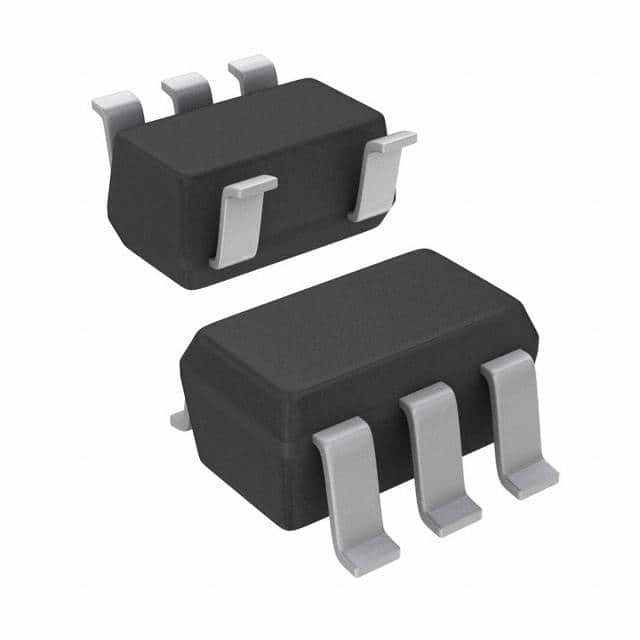
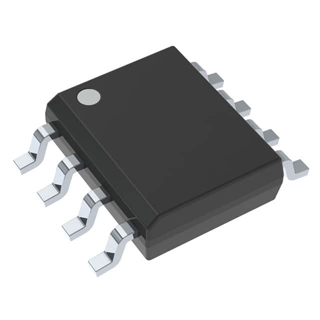
| Description | IC GATE DRVR LOW-SIDE SOT23-5 | IC GATE DRVR LOW-SIDE 8SOIC |
| Package | Cut Tape (CT) | Cut Tape (CT) |
| Series | - | - |
| Voltage - Supply | 4V ~ 14V | 3.5V ~ 14V |
| Operating Temperature | -40°C ~ 125°C (TA) | -40°C ~ 125°C (TJ) |
| Mounting Type | Surface Mount | Surface Mount |
| Package / Case | SC-74A, SOT-753 | 8-SOIC (0.154\", 3.90mm Width) |
| Supplier Device Package | SOT-23-5 | 8-SOIC |
| Input Type | Inverting | Inverting, Non-Inverting |
| Channel Type | Single | Independent |
| Rise / Fall Time (Typ) | 14ns, 14ns | 14ns, 12ns |
| Driven Configuration | Low-Side | Low-Side |
| Number of Drivers | 1 | 2 |
| Gate Type | N-Channel MOSFET | N-Channel MOSFET |
| Logic Voltage - VIL, VIH | 1V, 4V | 0.8V, 2.2V |
| Current - Peak Output (Source, Sink) | 2A, 2A | 3A, 5A |
| High Side Voltage - Max (Bootstrap) | - | - |
-
1. How to choose a gate driver for a MOSFET?
When selecting a gate driver for a MOSFET, the following key factors need to be considered:
Current drive capability: The current drive capability of the gate driver directly affects the turn-on and turn-off speed of the MOSFET. Higher current sinking and sourcing capabilities mean faster turn-on and turn-off speeds, thereby reducing switching losses.
Fault detection function: The gate driver should have fault detection functions such as undervoltage lockout (UVLO), desaturation (DESAT) detection, etc. to ensure the safety and stable operation of the system.
Interference immunity: Common mode transient immunity (CMTI) is an important parameter to measure the anti-interference ability of the gate driver. In high-power systems, high CMTI values can better resist voltage transients and ensure stable operation of the system.
Electrical isolation: Electrically isolated gate drivers can achieve electrical isolation between control signals and power devices to ensure system safety. Optical coupling isolation and magnetic coupling isolation are common electrical isolation technologies, and the selection should be compared according to application requirements.
Switching frequency: For high-frequency switching applications, the switching frequency of the gate driver should match the switching frequency of the MOSFET to ensure efficient operation.
Transmission delay: Transmission delay and transmission delay matching are important parameters of electrical isolation drivers, which affect the response speed of the signal and the stability of the system. -
2. What is an active gate driver?
An active gate driver is a circuit that is mainly used to enhance the gate signal of a field effect transistor (MOSFET) or an insulated gate bipolar transistor (IGBT) so that the controller can better control the operation of these semiconductor switches. It controls the gate of MOSFET or IGBT by converting the signal output by the controller into high-voltage, high-current pulses, thereby improving the performance, reliability and service life of these devices.
-
3. What is a motor gate driver?
A motor gate driver is a circuit that is mainly used to enhance the gate signal of a field effect transistor (MOSFET) or an insulated gate bipolar transistor (IGBT) so that the controller can better control the operation of these semiconductor switches. It converts the low-voltage signal output by the controller into a high-voltage, high-current pulse signal to ensure that the MOSFET or IGBT can switch states stably and quickly within its operating range.
-
4. What is the difference between MOSFET and IGBT gate drivers?
The gate drivers of MOSFET and IGBT have significant differences in drive voltage, drive current, and drive mode.
Drive Voltage and Drive Current
MOSFET: The gate drive voltage of MOSFET is low, usually between 10V and 20V. Due to its structural characteristics, the driving current of MOSFET is also relatively small, which is suitable for using a smaller driving circuit.
IGBT: The gate driving voltage of IGBT is relatively high, usually between 15V and 20V. Due to its composite structure, IGBT requires a large driving current to control its conduction and cutoff, and usually requires a special driving circuit to provide sufficient driving power.
Driving method
MOSFET: The switching speed of MOSFET is very fast and suitable for high-frequency applications. Its driving method is relatively simple, and the gate can be directly controlled by voltage to achieve fast switching action.
IGBT: The switching speed of IGBT is slow and suitable for low-frequency applications. Due to its composite structure, IGBT requires a larger driving current and a more complex driving circuit to ensure its stable operation. IGBT usually requires positive and negative voltages to control its conduction and cutoff, especially when it is turned off, a negative voltage is required to eliminate the current tailing effect.
