Texas Instruments CDC509PWRG4

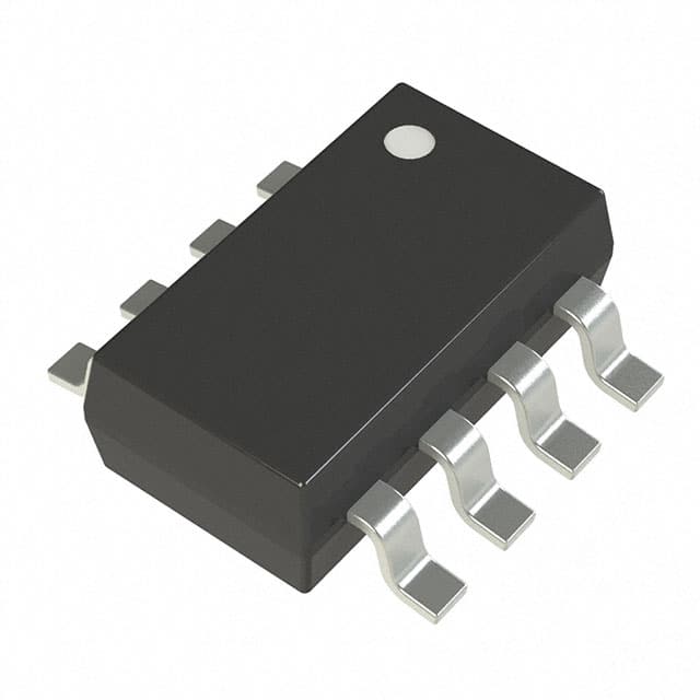
The picture is for reference only, please refer to the product specification
- CDC509PWRG4
- Texas Instruments
- IC 3.3V PLL CLOCK DRVR 24-TSSOP
- Clock/Timing - Clock Generators, PLLs, Frequency Synthesizers
- CDC509PWRG4 Datasheet
- 24-TSSOP (0.173\", 4.40mm Width)
- Cut Tape (CT)
-
 Lead free / RoHS Compliant
 - 9925
- Spot Inventory / Athorized Dstributor / Factory Excess Stock
- 1 year quality assurance 》
- Click to get rates


What is CDC509PWRG4
Texas Instruments Part Number CDC509PWRG4(Clock/Timing - Clock Generators, PLLs, Frequency Synthesizers), developed and manufactured by Texas Instruments, distributed globally by Jinftry. We distribute various electronic components from world-renowned brands and provide one-stop services, making us a trusted global electronic component distributor.
CDC509PWRG4 is one of the part numbers distributed by Jinftry, and you can learn about its specifications/configurations, package/case, Datasheet, and other information here. Electronic components are affected by supply and demand, and prices fluctuate frequently. If you have a demand, please do not hesitate to send us an RFQ or email us immediately [email protected] Please inquire about the real-time unit price, Data Code, Lead time, payment terms, and any other information you would like to know. We will do our best to provide you with a quotation and reply as soon as possible.
CDC509PWRG4 Specifications
- Part NumberCDC509PWRG4
- CategoryClock/Timing - Clock Generators, PLLs, Frequency Synthesizers
- ManufacturerTexas Instruments
- DescriptionIC 3.3V PLL CLOCK DRVR 24-TSSOP
- PackageCut Tape (CT)
- Series-
- TypePLL Clock Driver
- Voltage - Supply3V ~ 3.6V
- Operating Temperature0°C ~ 70°C
- Mounting TypeSurface Mount
- Package / Case24-TSSOP (0.173\", 4.40mm Width)
- Supplier Device Package24-TSSOP
- OutputLVTTL
- Frequency - Max125MHz
- Number of Circuits1
- InputLVTTL
- PLLYes with Bypass
- Ratio - Input:Output1:9
- Differential - Input:OutputNo/No
- Divider/MultiplierNo/No
Application of CDC509PWRG4
CDC509PWRG4 Datasheet
CDC509PWRG4 Datasheet , Cut Tape (CT),PLL Clock Driver,3V ~ 3.6V,0°C ~ 70°C,Surface Mount,24-TSSOP (0.173\", 4.40mm Width),24-TSSOP,LVTTL,125MHz,1,LVTTL,Yes with Bypass,1:9,No/No,No/No
CDC509PWRG4 Classification
Clock/Timing - Clock Generators, PLLs, Frequency Synthesizers
FAQ about Clock/Timing - Clock Generators, PLLs, Frequency Synthesizers
-
1. How does the output frequency of the PLL frequency synthesizer change?
The core of the PLL frequency synthesizer is to change the output frequency by adjusting the various components in the loop. The basic working principle of the PLL frequency synthesizer is to generate a stable frequency signal through the interaction of the phase detector, loop filter and voltage-controlled oscillator. When the output frequency needs to be changed, the control voltage of the voltage-controlled oscillator can be changed by adjusting the input signal or by an external control signal to adjust its output frequency.
-
2. Which is better, direct digital synthesis or PLL?
Direct digital synthesis (DDS) and PLL each have their own advantages and disadvantages. Choosing which one is better depends on the specific application requirements. DDS performs well in frequency switching speed and high resolution, while PLL has more advantages in phase noise and spurious performance.
The advantages of DDS include:
High frequency switching speed: DDS works in the digital domain. Once the frequency control word is updated, the output frequency changes accordingly, and the frequency hopping rate is high.
High resolution: Due to the large width of the frequency control word (such as 48bit or higher), the frequency resolution is high.
Flexibility: DDS can generate any desired waveform and initial phase, suitable for applications requiring a wide range of scenarios.
PLL advantages include:
Low phase noise: PLL excels in low phase noise and low spurious performance, suitable for applications requiring high stable frequency.
Wide frequency range: The upper limit of the PLL output frequency depends on the upper limit of the VCO, which can support a wider frequency range.
-
3. What are frequency synthesizers used for?
The main purpose of frequency synthesizers is to provide specific frequency signals for radio and communication systems. It is an important component of modern electronic systems and is widely used in communication, radar, navigation and other equipment.
Frequency synthesizers generate a large number of discrete frequencies with the same stability and accuracy from one or more reference signal sources with high frequency stability and accuracy through linear operations in the frequency domain. Specifically, frequency synthesizers use techniques such as frequency multiplication, frequency division, and mixing to obtain discrete frequency signals with the same stability as the reference signal.
We are a professional PCB manufacturer who offers comprehensive PCB manufacturing services including: professional Ceramic PCB HDI PCB Heavy Copper PCB High-TG PCB High Speed PCB High Frequency PCB Metal Core PCB PCB fabrication and PCB assembly, providing fast turnaround prototypes for high-end products.


• Prompt Responsiveness
• Guaranteed Quality
• Global Access
• Competitive Market Price
• One-Stop support services of supply chain
Jinftry, Your most trustworthy component supplier, welcome to send us the inquiry, thank you!
Do you have any questions about CDC509PWRG4 ?
Feel free to contact us:
CDC509PWRG4 Related Products

IC TRANSLATOR UNIV FREQ 56VFQFN

IC TRANSLATOR UNIV FREQ 56VFQFN


IC FREQ SYNTHESIZER 20-TSSOP

IC CLOCK GEN W/PLL 64-LFCSP