Maxim Integrated MAX11666AUB+

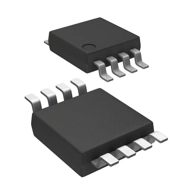
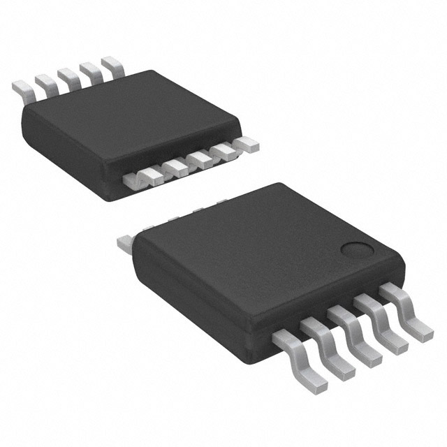
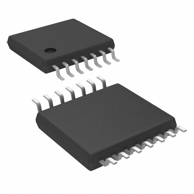
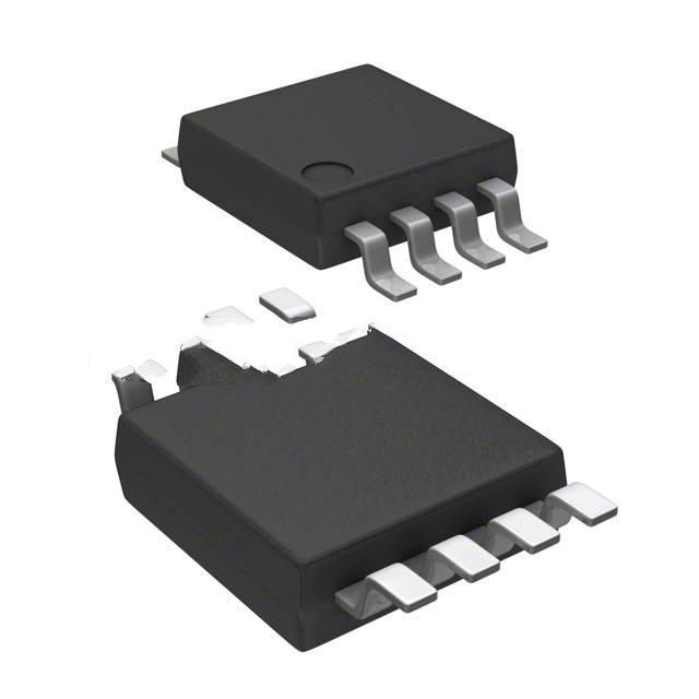
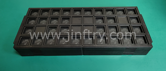
The picture is for reference only, please refer to the product specification
- MAX11666AUB+
- Maxim Integrated
- IC ADC 12BIT SAR 10UMAX
- Data Acquisition - Analog to Digital Converters (ADC)
- MAX11666AUB+ Datasheet
- 10-TFSOP, 10-MSOP (0.118\", 3.00mm Width) Exposed Pad
- Tube
-
 Lead free / RoHS Compliant
 - 4199
- Spot Inventory / Athorized Dstributor / Factory Excess Stock
- 1 year quality assurance 》
- Click to get rates


What is MAX11666AUB+
Maxim Integrated Part Number MAX11666AUB+(Data Acquisition - Analog to Digital Converters (ADC)), developed and manufactured by Maxim Integrated, distributed globally by Jinftry. We distribute various electronic components from world-renowned brands and provide one-stop services, making us a trusted global electronic component distributor.
MAX11666AUB+ is one of the part numbers distributed by Jinftry, and you can learn about its specifications/configurations, package/case, Datasheet, and other information here. Electronic components are affected by supply and demand, and prices fluctuate frequently. If you have a demand, please do not hesitate to send us an RFQ or email us immediately [email protected] Please inquire about the real-time unit price, Data Code, Lead time, payment terms, and any other information you would like to know. We will do our best to provide you with a quotation and reply as soon as possible.
MAX11666AUB+ Specifications
- Part NumberMAX11666AUB+
- CategoryData Acquisition - Analog to Digital Converters (ADC)
- ManufacturerMaxim Integrated
- DescriptionIC ADC 12BIT SAR 10UMAX
- PackageTube
- Series-
- Features-
- Operating Temperature-40°C ~ 125°C
- Mounting TypeSurface Mount
- Package / Case10-TFSOP, 10-MSOP (0.118\", 3.00mm Width) Exposed Pad
- Supplier Device Package10-uMAX-EP
- Reference TypeSupply
- Sampling Rate (Per Second)500k
- Data InterfaceSPI
- Number of Bits12
- Voltage - Supply, Analog2.2V ~ 3.6V
- Voltage - Supply, Digital2.2V ~ 3.6V
- Number of Inputs2
- Input TypeSingle Ended
- ConfigurationMUX-S/H-ADC
- Ratio - S/H:ADC1:1
- Number of A/D Converters1
- ArchitectureSAR
Application of MAX11666AUB+
MAX11666AUB+ Datasheet
MAX11666AUB+ Datasheet , Tube,-40°C ~ 125°C,Surface Mount,10-TFSOP, 10-MSOP (0.118\", 3.00mm Width) Exposed Pad,10-uMAX-EP,Supply,500k,SPI,12,2.2V ~ 3.6V,2.2V ~ 3.6V,2,Single Ended,MUX-S/H-ADC,1:1,1,SAR
MAX11666AUB+ Classification
Data Acquisition - Analog to Digital Converters (ADC)
FAQ about Data Acquisition - Analog to Digital Converters (ADC)
-
1. What process converts analog to digital?
There are three basic processes for analog to digital conversion:
The first process is "sampling", which is to extract the sample value of the analog signal at equal intervals to turn the continuous signal into a discrete signal.
The second process is called "quantization", which is to convert the extracted sample value into the closest digital value to represent the size of the extracted sample value.
The third process is "encoding", which is to represent the quantized value with a set of binary digits. After these three processes, the digitization of the analog signal can be completed. This method is called "pulse encoding".
After the digital signal is transmitted to the receiving end, a restoration process is required, that is, the received digital signal is converted back to an analog signal so that it can be understood by the receiver. This process is called "digital-to-analog conversion", which reproduces it as sound or image. -
2. How to convert analog to digital without ADC?
Analog to digital conversion without ADC can be achieved through PWM circuit. This method is suitable for those main control chips without built-in ADC, which needs to be solved by two GPIOs and an operational amplifier. The basic principle is to use an integral circuit to convert the PWM wave into a smooth DC voltage, and then continuously adjust the PWM duty cycle by comparing it with the voltage to be measured until the output of the comparator changes from 0 to 1, and record the current PWM duty cycle, thereby realizing the measurement of the analog voltage.
-
3. What is the difference between ADC and DAC?
The main difference between ADC and DAC is that they process different types of signals and conversion directions.
The main function of an ADC (analog-to-digital converter) is to convert analog signals into digital signals. This process involves sampling, quantization, and encoding, where sampling is the periodic measurement of the value of an analog signal at a certain sampling rate, quantization is the conversion of the sampled continuous values into a finite number of discrete levels, and encoding is the conversion of the quantized discrete levels into binary code. The output of the ADC is a digital signal that can be processed and stored by a computer or other digital circuit for various applications such as digital signal processing, data logging, and communications. Common applications in life include microphones, digital thermometers, digital cameras, etc., which convert the actual perceived analog information into digital signals for further processing and analysis12.
DAC (
We are a professional PCB manufacturer who offers comprehensive PCB manufacturing services including: professional Ceramic PCB HDI PCB Heavy Copper PCB High-TG PCB High Speed PCB High Frequency PCB Metal Core PCB PCB fabrication and PCB assembly, providing fast turnaround prototypes for high-end products.


• Prompt Responsiveness
• Guaranteed Quality
• Global Access
• Competitive Market Price
• One-Stop support services of supply chain
Jinftry, Your most trustworthy component supplier, welcome to send us the inquiry, thank you!
Do you have any questions about MAX11666AUB+ ?
Feel free to contact us:
MAX11666AUB+ Related Products


IC ADC 12BIT SAR 8VSSOP


IC ADC 10BIT SAR SOT23-6

IC ADC 10BIT SAR 6WSON


IC ADC 12BIT SAR 6WSON