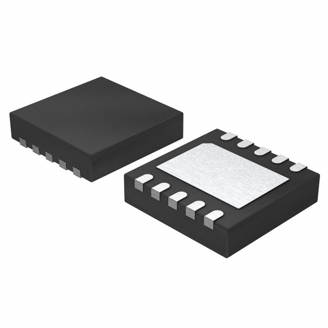
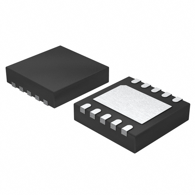
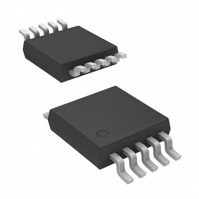
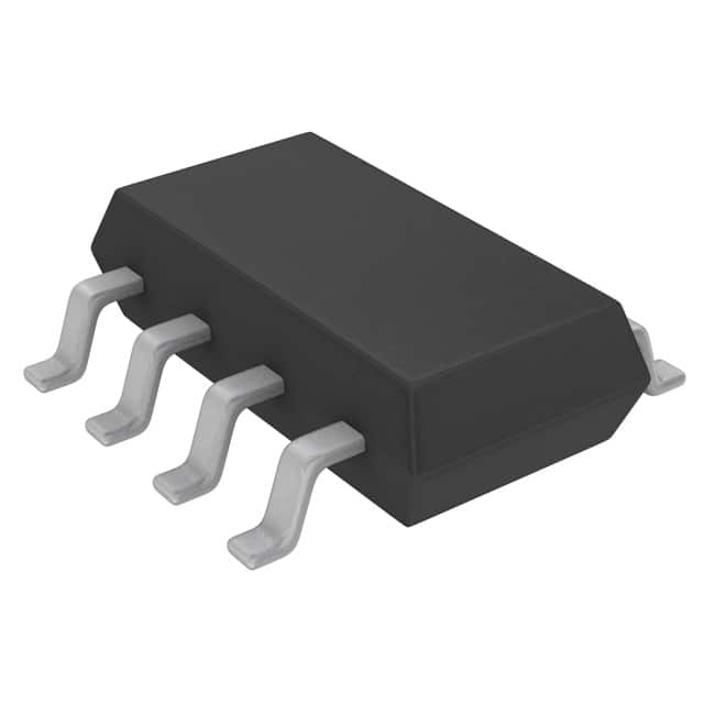
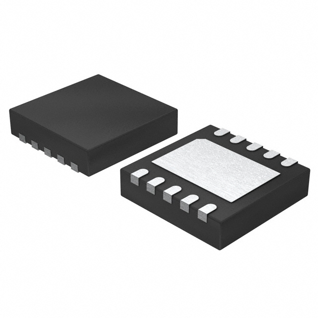
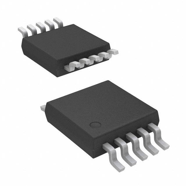
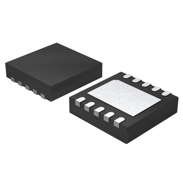
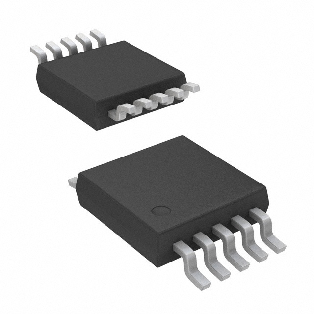
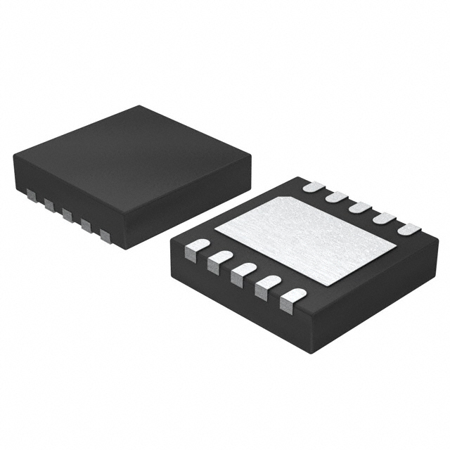
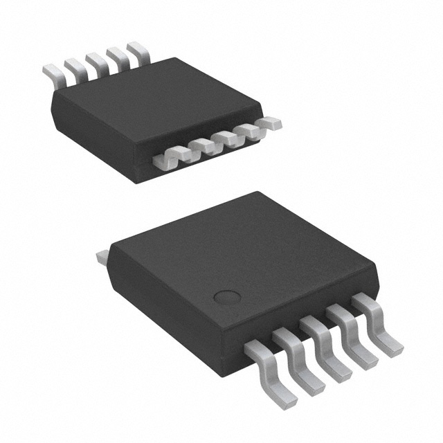
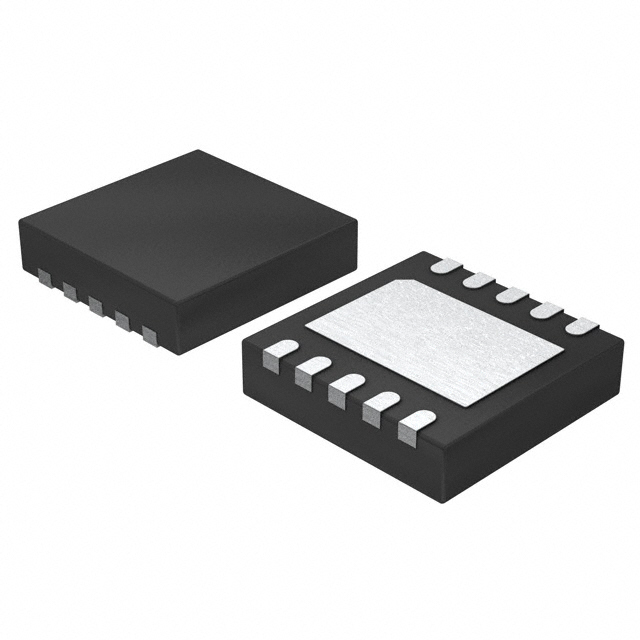
MCP33121-10-E/MN Product Introduction:
Microchip Technology Part Number MCP33121-10-E/MN(Data Acquisition - Analog to Digital Converters (ADC)), developed and manufactured by Microchip Technology, distributed globally by Jinftry. We distribute various electronic components from world-renowned brands and provide one-stop services, making us a trusted global electronic component distributor.
MCP33121-10-E/MN is one of the part numbers distributed by Jinftry, and you can learn about its specifications/configurations, package/case, Datasheet, and other information here. Electronic components are affected by supply and demand, and prices fluctuate frequently. If you have a demand, please do not hesitate to send us an RFQ or email us immediately sales@jinftry.com Please inquire about the real-time unit price, Data Code, Lead time, payment terms, and any other information you would like to know. We will do our best to provide you with a quotation and reply as soon as possible.
Introducing the Microchip Technology MCP33121-10-E/MN, a high-performance 16-bit Analog-to-Digital Converter (ADC) designed to meet the demanding requirements of industrial and automotive applications. With its exceptional accuracy and versatility, this ADC is the perfect solution for a wide range of measurement and control systems.
The MCP33121-10-E/MN boasts a resolution of 16 bits, providing precise and reliable conversion of analog signals into digital data. Its impressive sampling rate of 10 Mega samples per second ensures real-time data acquisition, enabling fast and accurate measurements. Additionally, the low power consumption of this ADC makes it an ideal choice for battery-powered applications.
This ADC features a wide input voltage range of ±10V, allowing it to handle a variety of signal levels. Its differential inputs provide excellent noise rejection, ensuring accurate measurements even in noisy environments. The MCP33121-10-E/MN also includes a built-in voltage reference, eliminating the need for external components and simplifying the design process.
The MCP33121-10-E/MN is well-suited for a range of applications, including industrial automation, motor control, power monitoring, and automotive systems. Its high accuracy and fast conversion speed make it an excellent choice for precision measurement and control tasks. Whether you need to monitor temperature, pressure, or voltage, this ADC will deliver reliable and accurate results.
In conclusion, the Microchip Technology MCP33121-10-E/MN is a high-performance 16-bit ADC that offers exceptional accuracy, versatility, and low power consumption. With its wide input voltage range and differential inputs, it is the perfect choice for a variety of industrial and automotive applications.
Analog to digital Converters (ADCs) are electronic devices used to convert continuously varying Analog signals into discrete Digital signals. This process usually includes three steps: sampling, quantization and coding. Sampling means capturing the instantaneous value of an analog signal at a fixed frequency; Quantization approximates these transient values to the nearest discrete level; Finally, the encoding converts the quantized value into binary numeric form.
Application
ADCs(Analog-to-digital Converters) is widely used in a variety of scenarios, such as audio and video recording, measuring instruments, wireless communications, medical devices, and automotive electronics. For example, in audio devices, the ADC is responsible for converting the sound signal captured by the microphone into a digital format for easy storage and transmission.
FAQ about Data Acquisition - Analog to Digital Converters (ADC)
-
1.
How many types of ADC are there?
The types of ADC (Analog-to-Digital Converter) mainly include:
1. Integral ADC: Its working principle is to convert the input voltage into time (pulse width signal) or frequency (pulse frequency), and then obtain the digital value by the timer/counter. The advantage of the integral ADC is that it can obtain high resolution with a simple circuit and has strong anti-interference ability, but the disadvantage is that the conversion rate is extremely low because the conversion accuracy depends on the integration time.
2. Successive approximation type (SAR ADC): The successive approximation ADC is one of the most common architectures. Its basic principle is to convert by gradually approximating the value of the analog input signal. The advantages of the successive approximation ADC are high speed and low power consumption. It is cheap at low resolution, but expensive at high precision.
3. Parallel comparison type/serial-parallel comparison type ADC: The parallel comparison type AD uses m
-
2. How to convert analog to digital without ADC?
Analog to digital conversion without ADC can be achieved through PWM circuit. This method is suitable for those main control chips without built-in ADC, which needs to be solved by two GPIOs and an operational amplifier. The basic principle is to use an integral circuit to convert the PWM wave into a smooth DC voltage, and then continuously adjust the PWM duty cycle by comparing it with the voltage to be measured until the output of the comparator changes from 0 to 1, and record the current PWM duty cycle, thereby realizing the measurement of the analog voltage.
-
3. What is the principle of analog-to-digital converters?
The working principle of the analog-to-digital converter (ADC) is to convert analog signals into digital signals through four processes: sampling, holding, quantization, and encoding.
The main components of the analog-to-digital converter include samplers and quantizers, which work together to convert continuous analog signals into discrete digital signals. This process requires a reference analog quantity as a standard, and the maximum convertible signal size is usually used as the reference standard. The basic principles of the analog-to-digital converter can be summarized as follows:
Sampling: The analog-to-digital converter first samples the input analog signal through a sampling circuit, that is, discretizes the analog signal on the time axis.
Holding: The sampled signal is held by the holding circuit for the next quantization and encoding process.
Quantization: The quantization process is to divide the amplitude of the sampled and held analog signal into a finite number of le
 Lead free / RoHS Compliant


