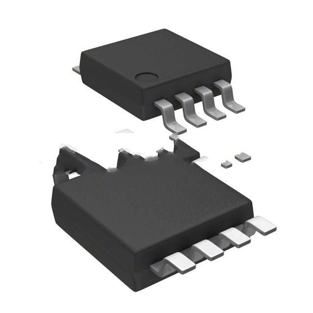
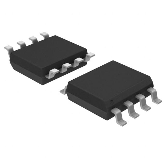
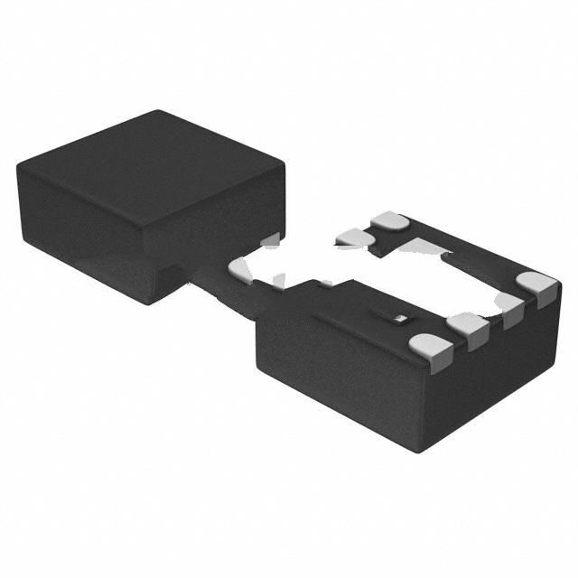
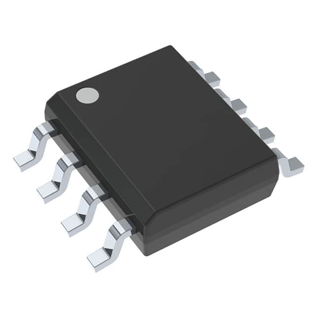
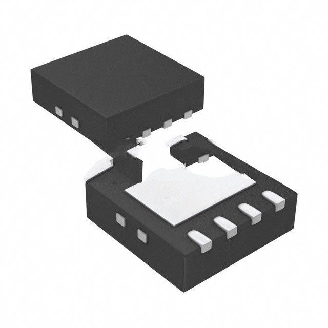
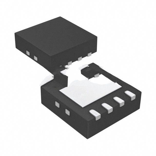
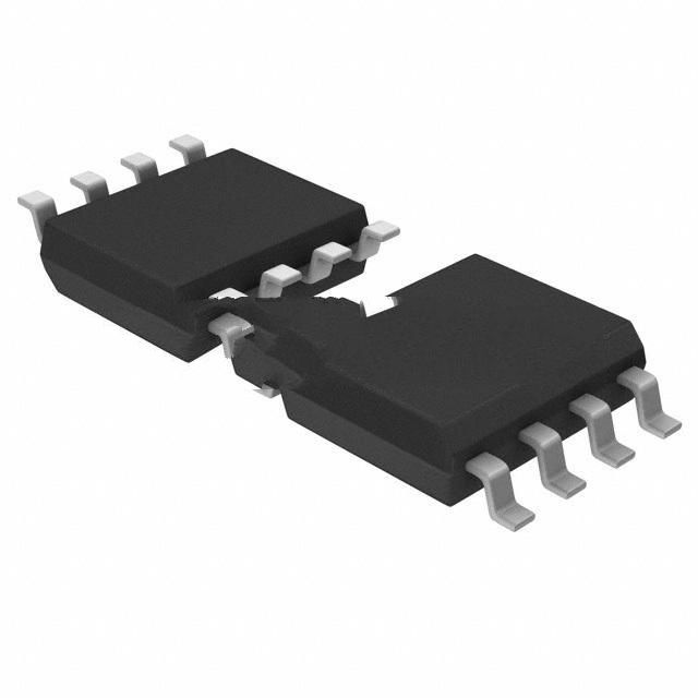
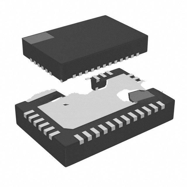
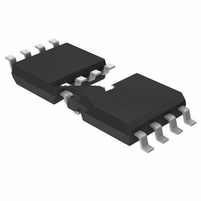
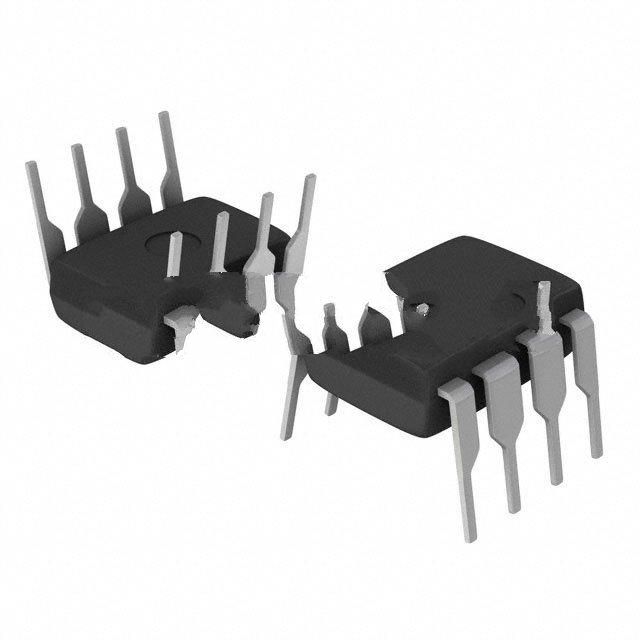
NCP81071AZR2G Product Introduction:
ON Semiconductor Part Number NCP81071AZR2G(PMIC - Gate Drivers), developed and manufactured by ON Semiconductor, distributed globally by Jinftry. We distribute various electronic components from world-renowned brands and provide one-stop services, making us a trusted global electronic component distributor.
NCP81071AZR2G is one of the part numbers distributed by Jinftry, and you can learn about its specifications/configurations, package/case, Datasheet, and other information here. Electronic components are affected by supply and demand, and prices fluctuate frequently. If you have a demand, please do not hesitate to send us an RFQ or email us immediately sales@jinftry.com Please inquire about the real-time unit price, Data Code, Lead time, payment terms, and any other information you would like to know. We will do our best to provide you with a quotation and reply as soon as possible.
Introducing the onsemi NCP81071AZR2G, a highly efficient synchronous buck converter designed to meet the demanding power requirements of modern electronic devices. With its advanced features and versatile application fields, this product is set to revolutionize the power management industry.
The NCP81071AZR2G boasts an impressive efficiency of up to 95%, ensuring minimal power loss and maximum energy savings. Its wide input voltage range of 4.5V to 18V makes it suitable for a wide range of applications, from consumer electronics to industrial equipment.
Equipped with a built-in high-side and low-side MOSFET, this buck converter eliminates the need for external components, simplifying the design process and reducing overall system cost. Its adjustable switching frequency allows for flexible optimization, ensuring optimal performance in various operating conditions.
The NCP81071AZR2G also features a comprehensive set of protection mechanisms, including overcurrent protection, thermal shutdown, and undervoltage lockout, ensuring the safety and reliability of your system.
With its compact size and robust design, the NCP81071AZR2G is ideal for a wide range of applications, including smartphones, tablets, laptops, LED lighting, and industrial automation. Its high efficiency and advanced features make it the perfect choice for power management in today's demanding electronic devices.
Experience the power of the onsemi NCP81071AZR2G and unlock the full potential of your electronic devices.
Gate Drivers are circuits specifically designed to enhance and control the gate signals of a MOSFET or IGBT. It receives low-voltage and low-current signals from the controller and converts them into high-voltage and high-current pulse signals that directly act on the gate of the MOSFET or IGBT, thus achieving accurate control of these semiconductor switching devices. Grid drivers have become an indispensable part of modern power electronic systems because of their high efficiency in signal conversion and stable driving performance.
Application
Gate Drivers have been widely used in various fields of power electronics technology. In the motor control system, the gate driver is used to drive the MOSFET or IGBT switching components of the inverter to achieve accurate control and efficient operation of the motor, which is widely used in the fields of electric vehicles, industrial automation equipment and household appliances. In power inverters, the gate driver is responsible for converting DC power to AC power to meet the needs of various loads, commonly seen in solar photovoltaic systems, wind power systems and uninterruptible power supplies (UPS). In addition, gate drivers also play an important role in many fields such as switching power supplies, AC frequency converters, and power electronic converters.
FAQ about PMIC - Gate Drivers
-
1. What is a gate driver?
Circuit, gate signal enhancement, controller
A gate driver is a circuit that is mainly used to enhance the gate signal of a field effect transistor (MOSFET) or an insulated gate bipolar transistor (IGBT) so that the controller can better control the operation of these semiconductor switches ,The gate driver controls the gate of the MOSFET or IGBT by converting the signal output by the controller into a high-voltage, high-current pulse, thereby improving the performance, reliability and service life of these devices.
Working principle
The gate driver is mainly composed of an input stage, a driver stage and an output stage:
Input stage: responsible for receiving the signal output by the controller and converting it into a TTL or CMOS logic level.
Driver stage: amplifies and converts the signal to generate a high-voltage, high-current pulse signal.
Output stage: uses these pulse signals to control the gate of the MOSFET or IGBT.
-
2. What are the different types of gate drivers?
There are mainly the following types of gate drivers:
High-frequency high-voltage gate driver: This driver can drive two N-channel MOSFETs, supports a power supply voltage of up to 100V, has strong driving capabilities, is suitable for MOSFETs with high gate capacitance, and can reduce switching losses. It also has features such as undervoltage lockout and adaptive shoot-through protection.
HL-type gate driver: The HL-type driver drives two N-channel MOSFETs in a half-bridge configuration and supports a power supply voltage of up to 140V. It has independent control outputs and strong anti-interference ability, and is suitable for application scenarios that require independent control of two MOSFETs. The HL type driver also has functions such as UVLO, TTL/CMOS compatible input, adjustable turn-on/off delay and shoot-through protection.
Pulse transformer drive: This driver does not require a separate drive voltage, and applies a high voltage to the gate through a pulse transformer, which is suitable for half-bridge or full-bridge circuits. It uses a capacitor and pulse transformer in series to increase the switching speed, and quickly resets the pulse transformer through a Zener diode.
Optocoupler and floating power supply drive: This driver uses an optocoupler to isolate the microcontroller and power transistor, and requires a separate floating power supply. The optocoupler output requires a separate power supply, which is suitable for high-side drive of half-bridge or full-bridge.
Push-pull circuit: The push-pull circuit is suitable for situations where the drive current is insufficient. It provides sufficient drive current by alternating between two transistors, which is suitable for application scenarios that require high drive current.
Half-bridge/full-bridge high-end drive: This driver applies a high voltage to the gate, which is suitable for half-bridge or full-bridge circuits. Since the source voltage of the high-end MOSFET changes, it needs to be powered independently and cannot share a ground with the low-end MOSFET.
-
3. What is the difference between MOSFET and IGBT gate drivers?
The gate drivers of MOSFET and IGBT have significant differences in drive voltage, drive current, and drive mode.
Drive Voltage and Drive Current
MOSFET: The gate drive voltage of MOSFET is low, usually between 10V and 20V. Due to its structural characteristics, the driving current of MOSFET is also relatively small, which is suitable for using a smaller driving circuit.
IGBT: The gate driving voltage of IGBT is relatively high, usually between 15V and 20V. Due to its composite structure, IGBT requires a large driving current to control its conduction and cutoff, and usually requires a special driving circuit to provide sufficient driving power.
Driving method
MOSFET: The switching speed of MOSFET is very fast and suitable for high-frequency applications. Its driving method is relatively simple, and the gate can be directly controlled by voltage to achieve fast switching action.
IGBT: The switching speed of IGBT is slow and suitable for low-frequency applications. Due to its composite structure, IGBT requires a larger driving current and a more complex driving circuit to ensure its stable operation. IGBT usually requires positive and negative voltages to control its conduction and cutoff, especially when it is turned off, a negative voltage is required to eliminate the current tailing effect.
 Lead free / RoHS Compliant


