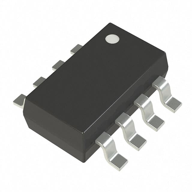
Texas Instruments TLC3574IDWR

The picture is for reference only, please refer to the product specification
- TLC3574IDWR
- Texas Instruments
- IC ADC 14BIT SAR 20SOIC
- Data Acquisition - Analog to Digital Converters (ADC)
- TLC3574IDWR Datasheet
- 20-SOIC (0.295\", 7.50mm Width)
- Tape & Reel (TR)
-
 Lead free / RoHS Compliant
 - 3049
- Spot Inventory / Athorized Dstributor / Factory Excess Stock
- 1 year quality assurance 》
- Click to get rates


What is TLC3574IDWR
Texas Instruments Part Number TLC3574IDWR(Data Acquisition - Analog to Digital Converters (ADC)), developed and manufactured by Texas Instruments, distributed globally by Jinftry. We distribute various electronic components from world-renowned brands and provide one-stop services, making us a trusted global electronic component distributor.
TLC3574IDWR is one of the part numbers distributed by Jinftry, and you can learn about its specifications/configurations, package/case, Datasheet, and other information here. Electronic components are affected by supply and demand, and prices fluctuate frequently. If you have a demand, please do not hesitate to send us an RFQ or email us immediately [email protected] Please inquire about the real-time unit price, Data Code, Lead time, payment terms, and any other information you would like to know. We will do our best to provide you with a quotation and reply as soon as possible.
TLC3574IDWR Specifications
- Part NumberTLC3574IDWR
- CategoryData Acquisition - Analog to Digital Converters (ADC)
- ManufacturerTexas Instruments
- DescriptionIC ADC 14BIT SAR 20SOIC
- PackageTape & Reel (TR)
- Series-
- Features-
- Operating Temperature-40°C ~ 85°C
- Mounting TypeSurface Mount
- Package / Case20-SOIC (0.295\", 7.50mm Width)
- Supplier Device Package20-SOIC
- Reference TypeExternal
- Sampling Rate (Per Second)200k
- Data InterfaceSPI
- Number of Bits14
- Voltage - Supply, Analog5V
- Voltage - Supply, Digital2.7V ~ 5.5V
- Number of Inputs2, 4
- Input TypePseudo-Differential, Single Ended
- ConfigurationMUX-S/H-ADC
- Ratio - S/H:ADC1:1
- Number of A/D Converters1
- ArchitectureSAR
Application of TLC3574IDWR
TLC3574IDWR Datasheet
TLC3574IDWR Datasheet , Tape & Reel (TR),-40°C ~ 85°C,Surface Mount,20-SOIC (0.295\", 7.50mm Width),20-SOIC,External,200k,SPI,14,5V,2.7V ~ 5.5V,2, 4,Pseudo-Differential, Single Ended,MUX-S/H-ADC,1:1,1,SAR
TLC3574IDWR Classification
Data Acquisition - Analog to Digital Converters (ADC)
FAQ about Data Acquisition - Analog to Digital Converters (ADC)
-
1. How does ADC convert analog to digital?
The technology that converts analog sound signals into digital signals is called analog-to-digital conversion technology (Analog to Digital Converter, referred to as ADC). The function of ADC is to convert continuously changing analog signals into discrete digital signals. The process of analog-to-digital conversion can be completed by steps such as sampling, holding, quantization, and encoding.
-
2. How many types of ADC are there?
The types of ADC (Analog-to-Digital Converter) mainly include:
1. Integral ADC: Its working principle is to convert the input voltage into time (pulse width signal) or frequency (pulse frequency), and then obtain the digital value by the timer/counter. The advantage of the integral ADC is that it can obtain high resolution with a simple circuit and has strong anti-interference ability, but the disadvantage is that the conversion rate is extremely low because the conversion accuracy depends on the integration time.
2. Successive approximation type (SAR ADC): The successive approximation ADC is one of the most common architectures. Its basic principle is to convert by gradually approximating the value of the analog input signal. The advantages of the successive approximation ADC are high speed and low power consumption. It is cheap at low resolution, but expensive at high precision.
3. Parallel comparison type/serial-parallel comparison type ADC: The parallel comparison type AD uses m -
3. How to convert analog to digital without ADC?
Analog to digital conversion without ADC can be achieved through PWM circuit. This method is suitable for those main control chips without built-in ADC, which needs to be solved by two GPIOs and an operational amplifier. The basic principle is to use an integral circuit to convert the PWM wave into a smooth DC voltage, and then continuously adjust the PWM duty cycle by comparing it with the voltage to be measured until the output of the comparator changes from 0 to 1, and record the current PWM duty cycle, thereby realizing the measurement of the analog voltage.
We are a professional PCB manufacturer who offers comprehensive PCB manufacturing services including: professional Ceramic PCB HDI PCB Heavy Copper PCB High-TG PCB High Speed PCB High Frequency PCB Metal Core PCB PCB fabrication and PCB assembly, providing fast turnaround prototypes for high-end products.


• Prompt Responsiveness
• Guaranteed Quality
• Global Access
• Competitive Market Price
• One-Stop support services of supply chain
Jinftry, Your most trustworthy component supplier, welcome to send us the inquiry, thank you!
Do you have any questions about TLC3574IDWR ?
Feel free to contact us: