A brief introduction to thick film electrical appliances VS thin film resistors
A brief introduction to thick film electrical appliances VS thin film resistors
Thin Film Resistors Overview
Thick Film Resistors Overview
Videos related to Thin Film Resistors vs Thick Film Resistors
Thin film resistor construction
Thin film resistor construction
Thin film resistor manufacturing
Thick Film Resistor Manufacturing
Thin film technology VS thick film technology
Thin and Thick Film Properties
Thin Film Resistors VS Thick Film Resistors
Thin Film Resistor Technology Overview
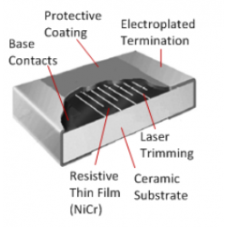
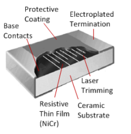
Thin Film Chip Resistor Schematic The resistive layer is sputtered (vacuum deposited) onto a ceramic substrate. This results in a uniform metal film approximately 0.1 micron thick. An alloy of nickel and chromium (nichrome) is usually used. Thin film resistors are available in different layer thicknesses to accommodate different ranges of resistance values. This layer is dense and uniform, suitable for trimming resistance values through subtractive processes. Use photolithography or laser trimming to create patterns in the film to add resistive paths and calibrate resistance values. The base is usually alumina ceramic, silicon or glass. Typically films are produced as chip or SMD resistors, but films can also be applied to cylindrical bases with axial leads. In this context, the term "metal film resistor" is more commonly used.
Thin film resistor construction
Thin film and thick film resistors are the most common types on the market. They feature a resistive layer on a ceramic base. Although they may look very similar, their properties and manufacturing processes are quite different. The name comes from the different layer thicknesses. Thin films are about 0.1 um (microns) or less thick, while thick films are thousands of times thicker. However, the main difference lies in the method of applying the resistive film to the substrate. Thin film resistors have a metal film deposited in a vacuum on an insulating substrate. Thick film resistors are made by firing a special paste onto a substrate. The slurry is a mixture of glass and metal oxides. The film has higher precision, better temperature coefficient and more stability. Therefore, it competes with other high-precision technologies such as wirewound or bulk metal foil. On the other hand, for these applications where high requirements are not important, thick film is preferred because the price is much lower.
Thin films are often used in precision applications. They have relatively high tolerances, low temperature coefficients and low noise. Furthermore, for high-frequency applications, thin films perform better than thick films. Inductance and capacitance are generally low. The parasitic inductance of the film will be higher if it is made into a cylindrical spiral (metal film resistor). The higher performance of thin film resistors comes with cost, which may be a factor in the higher price than thick film resistors. Typical examples where thin film resistors are used include medical equipment, audio equipment, precision control and measurement equipment.
Overview of Thick Film Electrical Technology
Schematic diagram of thick film chip resistors In the 1970s, thick film resistors became popular. Today, these resistors are by far the most commonly used resistors in electrical and electronic equipment. They are typically packaged as surface mount (SMD) chip resistors and offer the lowest cost compared to any other technology.
The resistive material is a special slurry made from a mixture of binder, carrier and metal oxide to be deposited. The adhesive is a glassy frit, and the carrier consists of an organic solvent system and plasticizer. Modern resistor pastes are based on oxides of ruthenium, iridium and rhenium. This is also called cermet (ceramic-metal). The resistive layer is printed onto the substrate at a temperature of 850 °C. The base material is typically 95% alumina ceramic. After firing the slurry on the carrier, the film becomes glassy, which makes it highly resistant to moisture. The complete firing process is shown in the picture below. Thickness is approximately 100 microns. This is about 1000 times that of thin films. Unlike thin films, this manufacturing process is additive. This means that resistive layers are sequentially added to the substrate to create conductive patterns and resistance values.

Temperature coefficients are typically in the range of 50 to 200 ppm/°C. Tolerances range from 1% to 5%. Because of their lower cost, thick films are generally preferred in applications that allow for greater resistance value tolerance, higher TCR, or lower stability. Therefore, these resistors can be found in almost any device with an AC plug or battery. The advantage of thick technology over thin technology is not only lower cost, but also the ability to handle more power, offer a wider range of resistance values, and withstand high surge conditions.
Thin film resistor construction
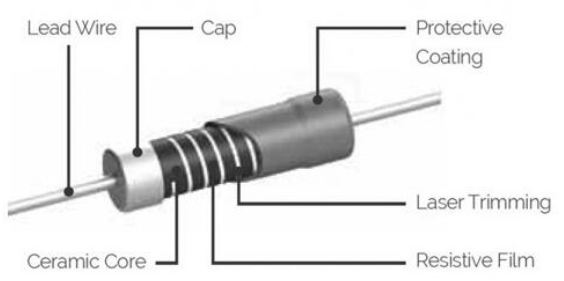
Thin film resistors can be made by sputtering resistive material on ceramic. The surface can then be etched using the desired etching technique and UV radiation. This resistor uses a number of different materials, including tantalum nitride, lead oxide, nickel chromium, and ruthenium oxide. Afterwards, the engraved film can be cut with a laser.

Thin film vs. thick film; what’s the difference?
The following table lists the main differences between the two technologies. The components may look the same, but the production methods and electrical performance are certainly different.
put up
Film thickness (microns) ±0.1 ±100
Manufacturing Processes Sputtering (Vacuum Deposition) Screen and Stencil Printing
Trim abrasive or laser for complex pattern photoetching abrasive or laser
Resistive Material A uniform metal film, usually a paste of nickel-chromium, ruthenium oxide, or other alloys.
Thin and Thick Film Properties
Resistance value (Ω) 0.2 – 20M 1 – 100M
Tolerance (%) ±0.1 - ±2 ±1 - ±5
Temperature coefficient (ppm/°C) ±5 - ±50 ±50 - ±200
Maximum operating temperature (°C) 155 155
Maximum operating voltage Umax (V) 50 - 500 50 - 200
Nonlinearity (dB) >110 >50
Current noise (μV/V) <0.1 <10
Rated power P 70 (W) 1/16 – 1 1/16 – 1/4
Stability at P 70 (1000 hours) ΔR/R % ±0.15 - ±0.5 ±1 - ±3
Moisture Resistance Thick films are more resistant to moisture because they resemble glass.
High Frequency Behavior Thin films have low parasitic inductance and capacitance. However, if the film is fabricated into a spiral-cut cylindrical shape, the inductance may be high.
Application areas
Typical areas of use High precision: measuring or monitoring equipment, medical or audio applications, precision control. Very broad: almost any electrical device with a battery or AC connection. The average PC contains over 1000 thick film chip resistors.
Comparison of Thin Film Resistors and Thick Film Resistors
First, the ruthenium oxide paste is screen-printed onto a ceramic substrate to create a thick film resistor element. Resistive elements are thousands of times thicker compared to thin film resistive elements. Standard tolerances are 1% and 5%, with typical TCR ranges from 100 ppm to 400 ppm. Although significantly more expensive than RMCF, the RGC series of semi-precision thick film chip resistors feature tolerances ranging from 0.5% to 50 ppm. After firing, thick film resistor elements take on the properties of glass, making them naturally waterproof.
Applications that require high stability, high accuracy, or low noise often use thin film resistors. Examples of such applications include instrumentation, precision control, monitoring, audio applications, and test and measurement equipment. Almost every electronic product uses thick film resistors; if it has a battery or AC plug, it probably does. For example, there are already more than 1200 chip resistors in ordinary PCs, most of which are thick film chip resistors. Before considering stability, accuracy, or noise, thick film resistors are always the preferred resistor choice in any circuit design.
Conclusion about thin film resistors and thick film resistors
Thin film resistors enable much lower tolerances, resistor temperature coefficients, noise, parasitic inductance and capacitance than thick film devices. Because of these superior qualities, thin film resistors have traditionally been much more expensive to produce than thick film resistors. However, advances in mass production methods and operating environments have significantly reduced the cost of producing high-quality, precision thin film chip resistors. Riedon's CAR Series resistors have a temperature coefficient rating of 25 ppm/°C with a tolerance of 0.01%.
The difference between thick film chip resistors and thin film chip resistors is mainly reflected in the following aspects:
Advantages and disadvantages of thin film resistors and thick film resistors
Materials and Manufacturing Process:
Thick Film Resistors: Using thick film technology, the resistive material is bonded to a ceramic base in a thicker layer. During the manufacturing process, a paste containing resistive materials is usually printed on the substrate through screen printing technology and then sintered at high temperature.
Thin Film Resistors: Using thin film technology, resistive materials are deposited into very thin layers. Thin films are usually made by physical or chemical deposition methods, such as vacuum evaporation or sputtering.
Performance features:
Thick film resistors: generally have higher power capabilities and better current handling capabilities. They have a larger temperature coefficient and are suitable for applications requiring higher power.
Thin Film Resistors: Provide greater accuracy and stability. They have a small temperature coefficient and are suitable for applications requiring high accuracy and stability.
Accuracy and Stability:
Thick film resistors: Relatively speaking, the accuracy is lower and the temperature drift is larger.
Thin film resistors: Can provide higher accuracy and smaller temperature coefficient, suitable for precision electronic equipment.
Cost and Application:
Thick Film Resistors: Relatively low cost, suitable for applications that are cost sensitive and do not require precision control.
Thin film resistors: Although more expensive, they are commonly used in high-end and precision electronic equipment due to their high accuracy and stability.
Thin film resistors and thick film resistors Frequently encountered problems:
What is the difference between thin film resistors and thick film resistors?
Thin film resistors are formed by vacuum depositing a metal layer on an insulating substrate. A specific slurry is applied to a substrate by fire to form a thick film resistor. Mix metal oxides and glass to make a paste. The films are more stable, more precise, and have superior temperature coefficients.
Why is thin film better than thick film?
Films made from the material can be easily integrated into a variety of devices. Although the films are very hard and have high thermal stability, they are brittle. Organic materials, on the other hand, are strong but soft and have reasonable thermal stability.
What can thin film resistors be used for?
The use of thin film resistors is intended for high accuracy, low noise and highly stable applications. These applications may include a variety of instrumentation, including measurement, test, medical, monitoring, instrumentation, precision and audio applications. These resistors are used in precision applications. Other applications for these resistors include stabilizing voltage dividers, stabilizing references, ADCs or DACs, and stabilizing feedback loops. They can also be used to change the operation gain. The network structure of these resistors provides improved performance. Thin film resistors are used in areas that require higher precision, such as HVAC systems, audio computer chips, power converters, radio frequency applications, aerospace and medical industries, and telecommunications.
What can thick film resistors be used for?
Examples of such applications include instrumentation, precision control, monitoring, audio applications, and test and measurement equipment. Almost every electronic product uses thick film resistors; if it has a battery or AC plug, it probably does.
What are the two types of thin film resistors?
Metal film resistors come in two different types: thick-film types, in which the resistive element is a metal-based slurry that is heated and burned; and thin-film types, in which the resistive element is a vapor-deposited film of metal.
Related thin film resistor related models:
CRCW0603200RFKEA CRCW120647K0FKEA CRCW08055R10FKEA CRCW040249R9FKED CRCW040249R9FKEDHP ..
edit author:
![]()
Jinftry(Hong Kong registered company name: JING FU CAI (HONGKONG) INTERNATIONAL CO., LIMITED) is an electronic parts distributor selling latest electronic components including integrated circuits, IC electronics, IC integrated circuits, IGBT, IGBT modules, button battery LR44,discrete te semiconductors, circuit protection, capacitors, resistors, potentiometers, transformers, isolators, crystals , oscillators, resonators, power managers, connectors, switches, relays, sensors, optoelectronic devices, diodes, and various batteries. Welcome to purchase electronic components from brand manufacturers. To view the solutions, you can log in to https://www.jinftry.com/ for inquiries

