What are IGBTs? How to improve the thermal performance design of IGBT on PCB
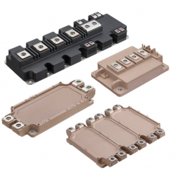
What are IGBTs? How to improve the thermal performance design of IGBT on PCB
IGBT - Insulated Gate Bipolar Transistor. An IGBT is a power semiconductor device used in high voltage and high current applications. They are mainly used as switches in power electronic circuits. It's worth noting in the name IGBT, which has an insulated gate like a FET and a bipolar transistor like a BJT. The main reason for this is that an IGBT is indeed a device that combines the advantages of both transistors (MOSFET and BJT in particular) and thus can be viewed from a semiconductor point of view
Basic knowledge of IGBTs:
Since an IGBT is a hybrid of a FET and a BJT, the symbol also represents this combination. A p-channel IGBT can also be expressed similarly

A comparison between the symbols for a MOSFET, BJT, and IGBT
IGBT This has collector and emitter terminals similar to a BJT, where the actual current flows, and has an insulated gate for switching.
The production and structure of IGBT:

The semiconductor structure of an IGBT
The entire structure was developed on an n-type substrate. Two p-bodies form on top. Inside the p-body there are two n+ wells to form the emitter terminal. The n-channel for current conduction is formed with the help of the top gate. The superscript "+" or "-" indicates the doping concentration, "+" indicates heavy doping, and "-" indicates light doping. The n layer in the center is a very important layer. Also known as the drift layer.
In the device structure, a p+ implanted layer is fabricated at the very end of the wafer where the collector terminal is formed. It is called an injection layer because it injects charge carriers (holes) into the n-drift layer to enhance current flow throughout the device
Characteristics of IGBT
The operating characteristics of GBT are similar to MOSFET and BJT,
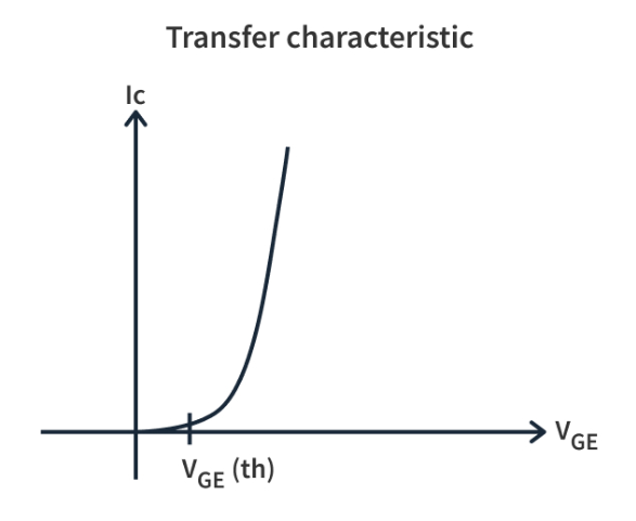
IGBT current vs. gate-emitter voltage
Static characteristics of IGBT are similar to BJT
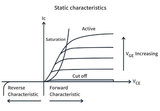
IV characteristics and operating area of IGBT
MOSFETs are faster switches, operating in the nanosecond range, while IGBTs are hundreds of nanoseconds. However, IGBTs are more suitable for high power applications such as switching amplifiers and industrial control systems, where they are more resilient in high voltage applications. This is why IGBTs are the first choice for electric vehicles and train traction equipment. Although relatively new compared to MOSFETs and BJTs, IGBTs continue to be used in a variety of applications due to their unique combination of relatively fast switching speeds and high voltage thresholds.
How to improve the thermal performance design of IGBT on PCB
IGBTs (Insulated Gate Bipolar Transistors) are widely used in power electronics and are key components in power conversion and control systems. In practical applications, due to the working characteristics of the IGBT, it will generate a certain amount of heat. If the heat dissipation system is not properly designed, it may cause overheating of the device, lower efficiency, or even damage. Therefore, a reasonable thermal design is particularly important.
This article will discuss how to improve the thermal performance design of IGBT on PCB from the following aspects:
Choice of thermally conductive material
Selecting materials with high thermal conductivity can effectively improve the heat dissipation effect of the IGBT. For example, copper is a common thermal conductivity material, and its thermal conductivity is much higher than that of other materials. Therefore, copper-based substrates or copper thermal conductivity layers can be selected in PCB design to increase thermal conductivity.
PCB stack-up design
Using a multi-layer PCB design, especially setting a thermal conductive layer or a thermal ground layer on the bottom layer, can effectively disperse heat. At the same time, the distance between IGBT and other sensitive components should be set reasonably to ensure that heat will not be transferred to other sensitive components.
heat sink design
For high power IGBT modules, an external heat sink is usually required to help dissipate heat. When designing the heat sink, it is necessary to ensure its fit with the IGBT, and the shape, size, and material of the heat sink must be reasonably selected to ensure the maximum heat dissipation effect.
Fans and Heat Sinks
In high-temperature environments or high-power operating conditions, a pure heat sink may not be able to meet the heat dissipation requirements. At this point, you can add a fan or heat sink to assist in heat dissipation. The fan can provide forced convection to accelerate heat transfer; while the heat sink can increase the heat exchange area and improve heat dissipation efficiency.
Thermal Interface Material (TIM)
Using high-quality thermal interface materials, such as thermal silica gel, thermal pad, etc., can fill the tiny gap between the IGBT and the heat sink to ensure effective heat transfer.
Cabling and Thermal Aisle
When designing the PCB, care should be taken to avoid the generation of heat channels. For the wiring of the IGBT module, try to choose a short and direct path to avoid generating additional heat. At the same time, avoid too much parallel wiring, because this will form a hot channel, resulting in excessive local temperature.
Thermal Simulation and Testing
After the design is completed, simulation software can be used for thermal simulation to predict the temperature distribution of the IGBT in actual work. In addition, actual thermal tests are performed to verify the validity of the design and make necessary adjustments based on the test results.
Environmental and Thermal Management
When installing the IGBT module, make sure there is enough heat dissipation space around it, and avoid placing it in a high temperature or closed environment. In addition, the cooling system should be checked and maintained regularly to ensure that it is always in good working condition.

In summary, the thermal performance design of IGBT on PCB is a complex and critical link. It is necessary to comprehensively consider various factors and adopt reasonable design methods and materials to ensure the stable, efficient and long-life operation of IGBT.
Jinftry company has the following models in stock (price advantage stock):
2MBI100VA-060-50,APT35GT120JU3,APT40GF120JRD,APT60GF60JU2 ,APTGF165A60D1G ,APTGF180DH60G ,APTGF50DDA120T3G,FZ800R12KE3 ,APT40GF120JRDQ2
2MBI150VA-060-50 ,2MBI150U2A-060-50 ,2MBI200U2A-060-50 ,2MBI200VA-060-50 ,2MBI300U2B-060-50 ,2MBI300VB-060-50 ,2MBI400U2B-060-50 ,2MBI400VB-060-50 ,2MBI600U2E-060 ,2MBI600VE-060
2MBI75U4A-120-50 ,2MBI75VA-120-50 ,2MBI100HB-120-50 ,2MBI100U4A-120-50 ,2MBI100VA-120-50 ,2MBI150VA-120-50 ,2MBI150U4B-120-50 ,2MBI150U4H-120-50 ,2MBI150VB-120-50 ,2MBI150HH-120-50
2MBI200U4B-120-50 ,2MBI200VB-120-50 ,2MBI200U4H-120-50 ,2MBI200VH-120-50 ,2MBI200HH-120-50 ,2MBI225U4N-120-50 ,2MBI225VN-120-50 ,2MBI300U4H-120-50 ,2MBI300VH-120-50 ....IGBT model spot
Welcome to consult
edit author:
![]()
Jinftry(Hong Kong registered company name: JING FU CAI (HONGKONG) INTERNATIONAL CO., LIMITED) was established in 2013, headquartered in Hong Kong, China, with a branch in Shenzhen, China. It is a global supplier of electronic components and a well-known and competitive electronic product distributor in Asia. Is also an excellent strategic partner of global ODM/OEM/EMS, able to quickly find authentic and traceable electronic components for customers to purchase.


