74LS32 Quad-2-Input OR Gate: Datasheet pdf, Circuit

The 74LS32 is a dual-input OR gate in a quad package. It contains four independent gates, each performing a logical OR function. This article will explain the datasheet pdf, pinout, application, circuit, working and other details about 74LS32 Logic Gate IC. Additionally, there is a large inventory of semiconductors, capacitors, resistors and ICs.
74LS32 Features:
Technology Series: LS
VCC (minimum): 4.75V
VCC (maximum): 5.25V
Number of channels: 4
Inputs per channel: 2
IOL (maximum): 0.8mA
IOH(max)-16mA
Input type: TTL compatible CMOS
Output type: push-pull
Features: High speed (TPD 10-50ns)
Data rate (maximum): 28Mbps
Rating: Catalog
Operating temperature range 0°C to 70°C
74LS32 equivalent product
Equivalent for 74LS32: CD4071
Other logic gates: 74LS00, 74LS08, 74LS02, 74LS04, 74HCT04
74LS32 Application
basic logic circuit
Encoders and decoders
Multiplexer and Demultiplexer
Oscillator circuit
Networks and digital systems
The main models of 74LS32 are: 74LS323PC, 74LS323SC, 74LS323SCX, 74LS32SC, 74LS32SCX
74LS32 circuit diagram and working principle
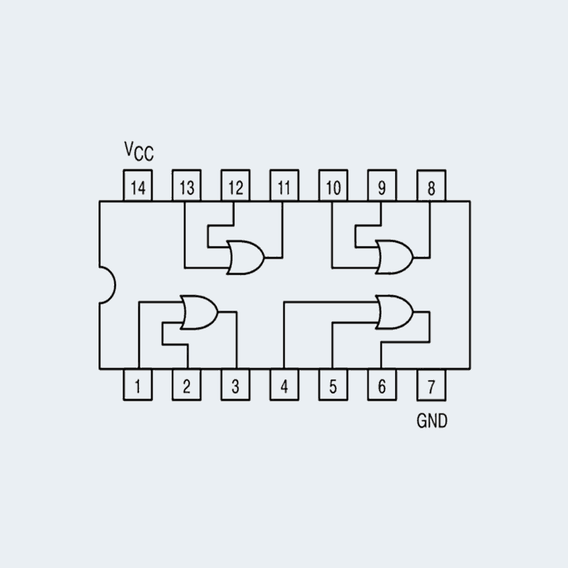
The output of the OR gate should be low only when both gate inputs are low, as shown in the truth table. Otherwise, the output should be set high. So if one or both inputs are high, the output of the OR gate will also be high.
We will use a 1K resistor to connect both gate inputs in the OR gate circuit to ground. Then connect the input to the power supply via the button. When the button is pressed, the corresponding pin of the gate input goes high. Therefore, it only takes two clicks to implement the truth table of the OR gate. When one of the buttons is pressed, one input of the gate will be high and the other low; the output should be high at this point. When both buttons are pressed, both inputs are high and the output of the OR gate is high at the same time.
When both buttons are released, both INPUTS of OR will be low and OUTPUT should also be low. Therefore, according to the truth table, the LED will only turn off when both buttons are released. If one or both buttons are pressed, the LED should light up.
Since the selected IC is a positive edge triggered IC, these pull-down resistors are required. If resistors are ignored, the circuit may have unforeseen effects. The capacitor in this circuit is used to counteract the bouncing effect of the button. While capacitors are not required, they can help the gate function more smoothly.


