Applications, challenges and opportunities of high-temperature components in the aviation field

Applications, challenges and opportunities of high-temperature components in the aviation field
High temperatures on aviation systems usually come from the following three sources:
1, it comes from the aircraft's power system, that is, the aircraft's engine and exhaust device. The temperature of the engine combustion chamber can reach several thousand degrees. The aircraft control system needs to monitor the combustion status in real time and control the combustion process by adjusting the ratio of fuel and air to achieve the highest combustion efficiency. In order to achieve efficient real-time monitoring and control of the engine, relevant sensors and electronic devices need to be as close to the engine as possible. Depending on the specific configuration location, they may need to withstand high temperatures of 300~600°C; |
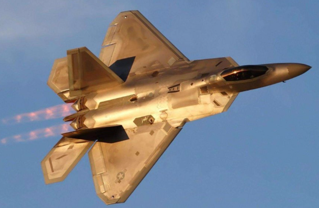
2, when the aircraft is flying at high speed, the friction between the aircraft surface and the air generates heat. When flying at supersonic speeds, the temperature on the surface of the aircraft can reach over 200°C. When an aircraft flying at supersonic speeds decelerates in the atmospheric environment, the heat generated by the pressure and friction of the air at the front of the aircraft is particularly large, and additional heat pumps are often required. protective layer;
3, the electronic components themselves generate heat. All electronic components have a certain amount of internal power dissipation. If the heat conduction and heat dissipation design is poor, especially in the thin air environment of high-altitude flight, the temperature rise inside the equipment will be too high, which will lead to very serious reliability problems.
In the face of heat sources and high-temperature environments on aircraft, in order to protect electronic components, the traditional approach is to try to avoid high-temperature areas when arranging electronic equipment, or to equip an external heating protection system, such as an Environment Control System (ECS). For example, in early centralized FADEC systems, sensor signals around the engine were fed to a remote central processing unit using shielded cables, and the central processing unit was usually installed in a temperature-controlled cabin with an air conditioner or cooling device. When all sensing and execution signals must be sent to a central processing unit for centralized processing, complex and huge wiring harnesses must be laid out on the aircraft, which not only takes up the valuable volume of the aircraft, but also increases the weight of the aircraft and brings More reliability and security issues.
Under certain restricted circumstances, temperature issues become a design bottleneck. For example, aircraft weapon systems are usually placed or mounted under the wings and fuselage, and their electronic control devices usually have no space to equip a cooling system; even if in some cases cooling devices, liquid pipelines and wiring harnesses can be configured, Will bring about complex reliability issues.

The selection of technical balance points has always been a complex and comprehensive consideration process in engineering design. At present, based on the performance of traditional bulk silicon semiconductors, aerospace applications generally set the ambient temperature limit standard at a maximum of 110°C, while the maximum junction temperature is below 125°C. In fact, many aerospace applications now control the junction temperature at about 60°C, mainly The reason is limited by the performance of bulk silicon semiconductor devices. Maintaining the temperature limits of electronic components is a significant burden on aircraft, especially in the wing area where space is limited. The cooling system usually takes up 10% of the weight of the aircraft (power is about 50KW), seriously affecting the overall performance of the aircraft. If the maximum allowable temperature of the case can be raised only to 150°C, and the junction temperature control temperature point can be appropriately raised, cooling devices and environmental control systems in some locations may no longer be needed. In this way, size, weight, power consumption and cost can be saved. In short, the high temperature resistance of electronic components has a great impact on the improvement of the overall performance of the aircraft.
When actually designing application systems, people are always limited by materials, and must make corresponding comprehensive considerations and compromises to achieve an acceptable design. It was by balancing the limits of materials and technology, just as by balancing the strength and weight of airframe materials, that the Wright brothers were able to achieve their first flight. After that, people continued to use new materials and new technologies to realize new aircraft designs at new balance points, and constantly improved and created new aircraft. This is the role of the avionics system. As an important component of modern aircraft, it is related to the aircraft's engine and flight status control, communications remote sensing and navigation, weapon systems (such as fire control, guidance and electronic countermeasures), etc. The application goals and environment of aircraft have special requirements for electronic components. Often new electronic devices can not only improve the efficiency of the aircraft, but also promote the realization of new design concepts. Therefore, high-temperature resistant electronic components have always been valued by the aerospace field.
Since the 1970s, digital, centralized FADEC based on mechanical, hydraulic drive and hybrid analog engine control has gone through more than 60 years and is now the standard configuration of various aircraft electronic control systems. In recent years, development in this field has shifted towards "distributed FADEC", mainly because:
Aircraft weight reduction requirements. Classic FADEC requirements require sensor signals to be transmitted back through bulky shielded wire harnesses. After calculation and processing by a central computer, instructions are issued to instruct the actuators to act. These transmissions require complex, expensive, and bulky multi-core wire harnesses and connectors, which take up a lot of space. The larger size and weight also bring more reliability problems; advanced aircraft are increasingly adopting distributed FADEC to achieve significant improvements. In a distributed FADEC system, signals often only need to be transmitted using a 4-wire lightweight wiring harness (a pair of differential digital signals, a pair of power and ground wires), which greatly simplifies the wiring harness and eliminates the vast majority of traditional aviation connectors. The extra pins not only simplify protection, but also significantly reduce the number and weight of connectors;
Distributed control requires sensors, actuators, and even its power management system to be as dispersed and close to the task site as possible. For example, engine signal measurement needs to be close to the engine (ambient temperature is as high as 300-600°C), while the wing action actuator needs to be close to the target wing, etc. These places often cannot be equipped with water-cooling mechanisms and can only rely on air cooling or natural cooling of the back panel of the machine. Therefore, the electrical system needs to be able to withstand high temperatures;
In addition, the electrification of actuators also makes distributed design easier to achieve, and its system response speed is much higher than that of traditional centralized system architecture. In the past, movements such as attitude adjustment and steering of aircraft were mainly achieved by hydraulic or pneumatic components. These components relied on precision mechanical coordination, resulting in high manufacturing costs, high failure rates and poor maintainability. However, motor-driven "solid-state" actuators have fast response times. , light weight and small size, low failure rate and high maintainability; it is estimated that the response time of the integrated motor actuator is only less than one-fifth of the hydraulic actuator, and the volume and weight of the same driving power are only the latter less than one-third. Due to volume, weight and reliability reasons, motor systems in aircraft are generally not allowed to be equipped with liquid cooling mechanisms and can only rely on air cooling and backplane natural cooling. Therefore, the high-temperature resistance of the power electronics they are equipped with faces great challenges.
The challenges faced by high-temperature components in the aviation field mainly include the following aspects:
Extreme temperature tolerance: Aerospace devices often need to operate at very high temperatures, which places extremely high demands on materials and design. Devices not only need to work properly in high-temperature environments, but also maintain stable performance.
Reliability and longevity: Device reliability is a major challenge under high temperature conditions. Long-term high temperature may cause material aging and performance degradation, so high temperature-resistant materials and optimized design are needed to extend device life.
Heat dissipation issue: In high-temperature environments, effective heat dissipation is the key to maintaining the normal operation of the device. Efficient heat dissipation technology needs to be developed to prevent devices from being damaged due to excessive temperatures.
Physical and chemical stability: High-temperature environments may cause changes in the physical and chemical properties of materials, such as expansion, corrosion, etc., which will affect the performance and life of the device.
Electromagnetic interference (EMI) resistance: In the complex aviation environment, devices need to have strong electromagnetic interference resistance to ensure that they can still work normally in high temperature and strong electromagnetic interference environments.
Manufacturing and testing technology: Device manufacturing and testing in high-temperature environments is a major challenge, requiring special technology and equipment to ensure device quality and performance.
Cost and resources: Developing aerospace devices suitable for high-temperature environments is usually costly, and cost-effectiveness and resource sustainability need to be considered.
These challenges require engineers and researchers to continuously innovate and improve technology to ensure the performance and reliability of aviation devices in extreme environments.
In short, in addition to the traditional need for high-temperature device support for aircraft systems due to their high-temperature environment (such as around the engine), in recent years, the trend of distributed control design of aircraft systems and the trend of the execution system changing from hydraulic and pneumatic transmission to motor transmission are all in Promoting new demands for high-temperature electronic technology, CISSOID focuses on the design and manufacturing of high-temperature SOI devices with a history of more than 20 years; currently it can provide more than 10 types and more than 100 models of high-temperature SOI devices, including diodes , MOSFETs, voltage references, voltage regulators, PWM controllers, gate drivers, analog-to-digital converters, comparators, operational amplifiers, logic devices , clock generators and timers, etc., according to different packaging forms, they are divided into Two series: CMT series is a high-temperature plastic package with a maximum junction temperature of 175°C; while the CHT series is a metal-ceramic package with a maximum junction temperature of 225°C. Based on the balanced die and package design and existing industrial process conditions, the high-temperature SOI devices currently provided by CISSOID can have a high-temperature working life of about 15 years (maximum junction temperature 175°C), or about 5.5 years (maximum junction temperature 225°C) ℃), or about 2.5 years (the maximum junction temperature is 250 ℃), and about 1.3 years (the maximum junction temperature is 280 ℃); the rule is that for every 25 ℃ temperature increase, the device life will be reduced by about half; at 300 When the temperature is above ℃, the SOI device still has a working life of several thousand hours.

